Miscellaneous Projects
Some Miscellaneous (PCB) Projects
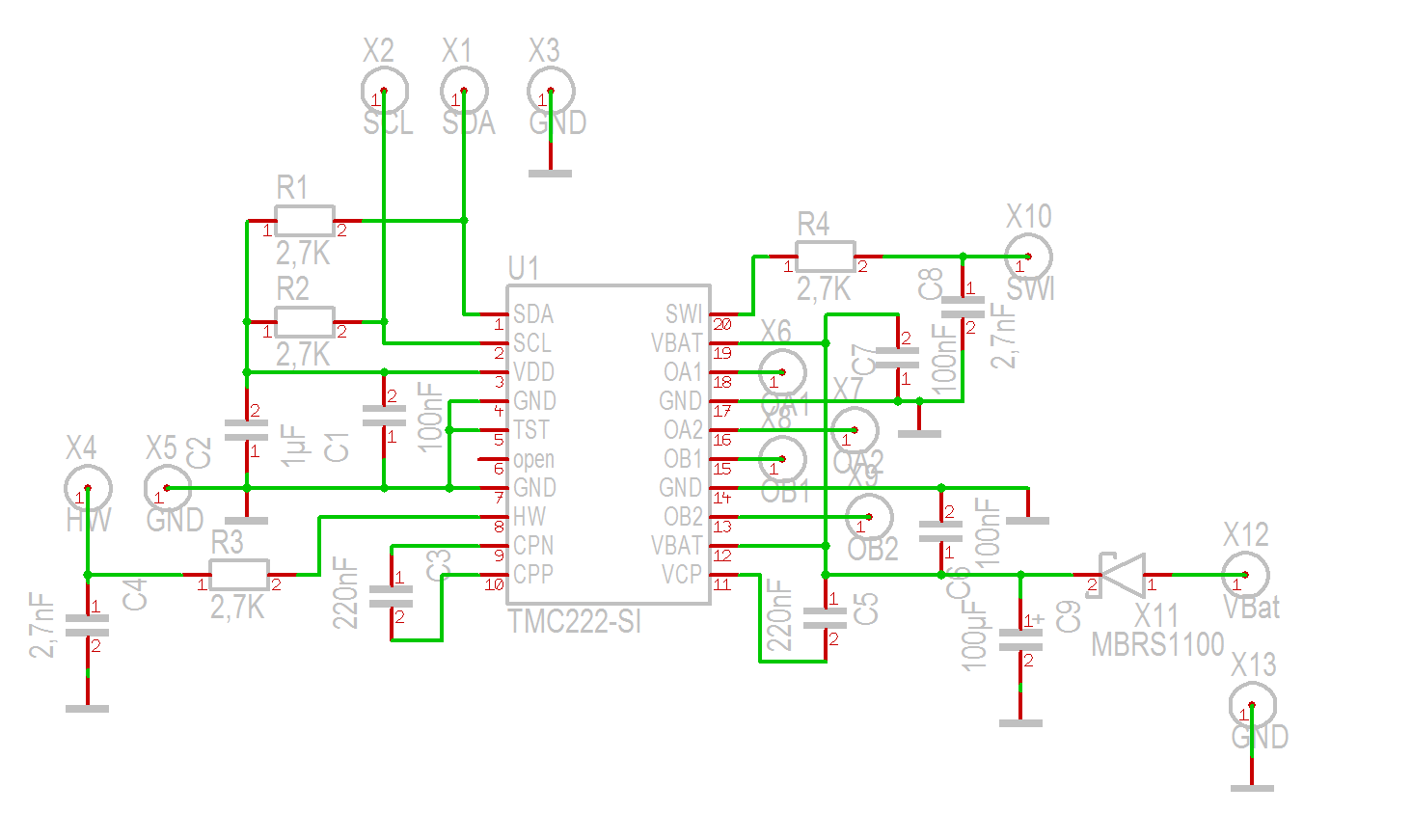
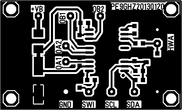
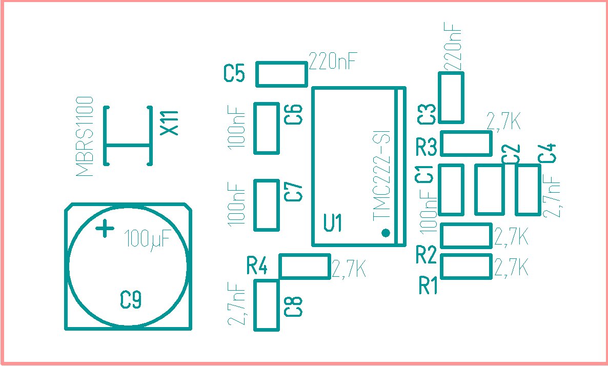
TMC222 Stepper motor controller, designed for Michel PE1PTS:
Splitter / diplexer for Transceiver - SDR-receiver:
I'm using this to simultaneously connect my Transceiver and SDR (Funcube Dongle Pro+) receiver to any SHF transverters, enabling receive and safe transmit. The unit provides 70dB or more isolation between TRX port and SDR port during transmit. On receive, the signal loss is just a little over 3dB thanks to the minicircuits 2-way splitter.
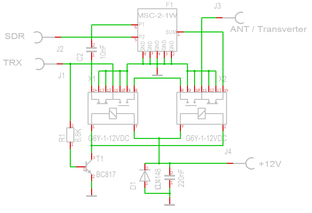
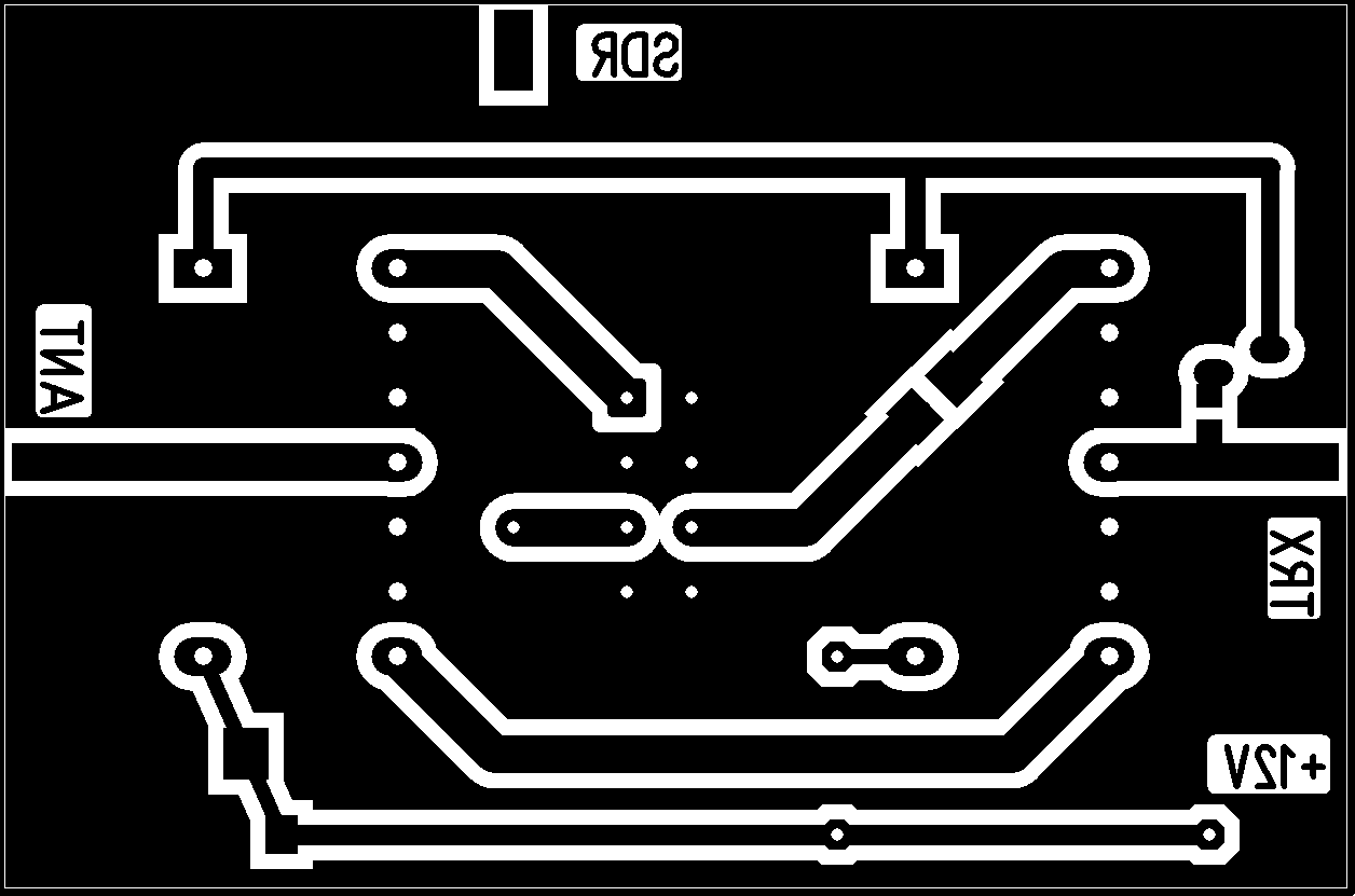
PCB dimensions: 55x35mm (fits in standard Schubert tinplated box 55x37x30mm)
Note: Tx (ptt) mode switching is done by a (weak, via 1kOhm) DC voltage on the Transceiver's antenna output. A feature that is used by all my SHF transverters, as soon as they sense the DC voltage on the 144MHz IF connection, they switch to TX mode.
AD8319 Log detector for power meter:
This small module was designed to accomodate the tiny AD8317 / AD8319 (2x3mm LFCSP) log dectector IC to be used in a SHF Power meter with a Directional coupler on 1,3 and 2,3GHz (see below for description of a simple self-made directional coupler).
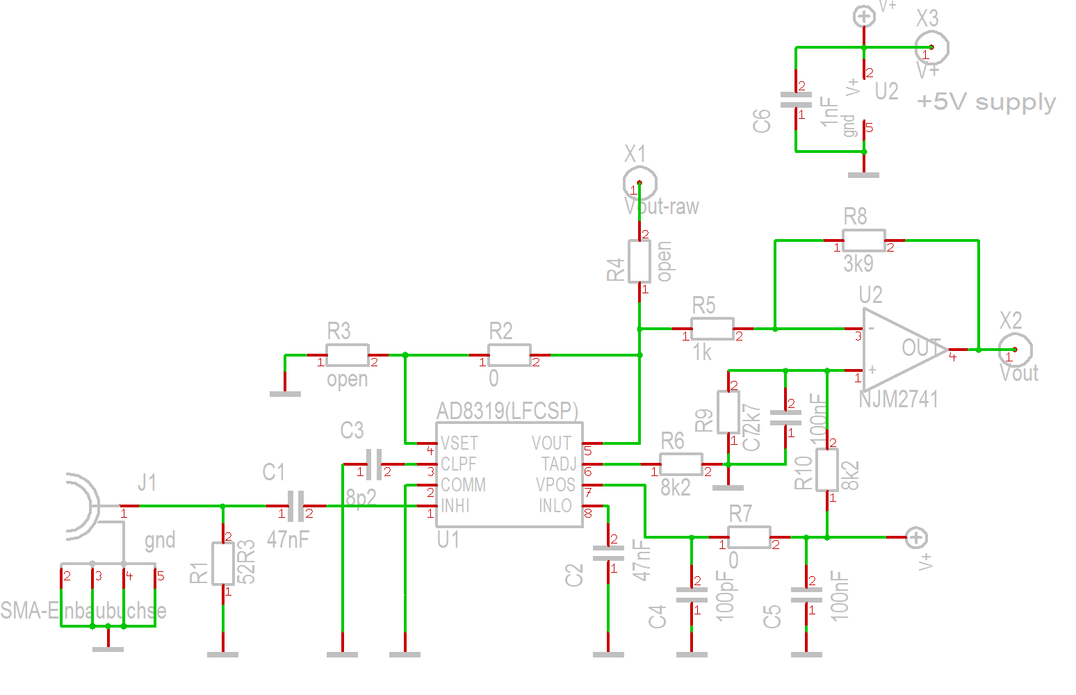
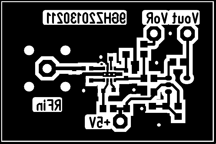
PCB Dimensions: 30x20mm
I made some measurements on this circuit: Results here
10MHz to 30MHz multiplier:
for IC706MkIIG Local Oscillator injection locking
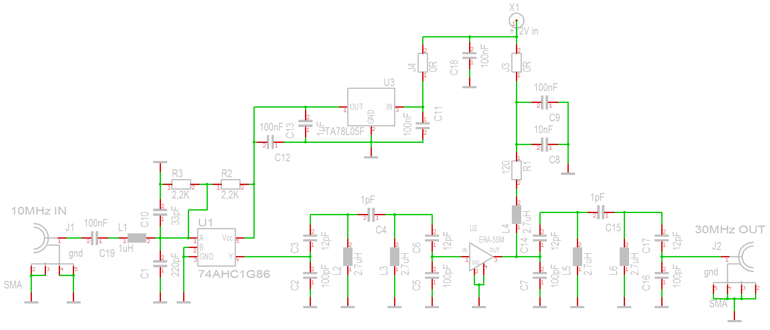
* 30MHz BandPassFilter values need some optimizing to obtain cleaner output spectrum.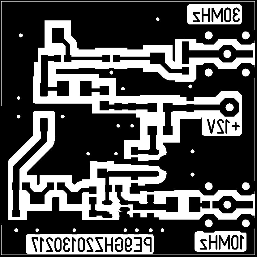
PCB dimensions: 35x35mm (fits in standard Schubert tinplated box 37x37x30mm)
PCB for ADL5902 ThruPower detector 50MHz-9GHz (>60dB dynamic range)
The ADL5902 in LFCSP-16 package features a higher dynamic range than the AD8319 (see above for AD8319 PCB project).
I've designed a PCB based on the eval board from Analog Devices (please refer to the datasheet at Analog.com)
and added a 10dB attenuator pad at the input (to increase max input power to 13dBm and to improve return loss)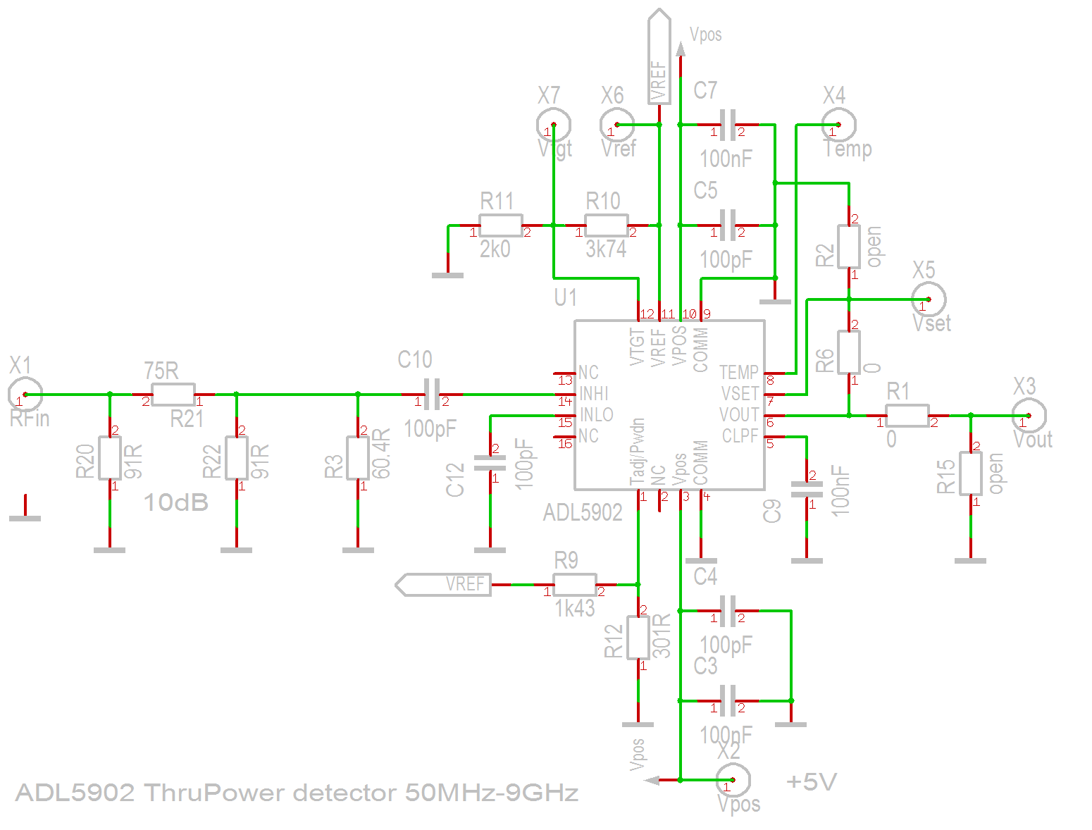
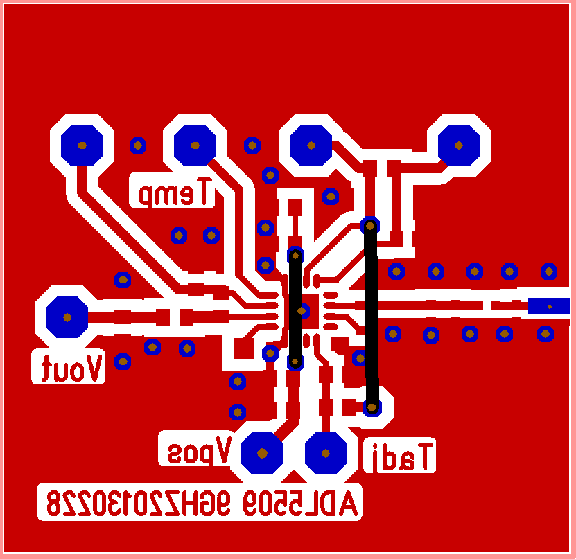
PCB dimensions: 34,9 x 34mm
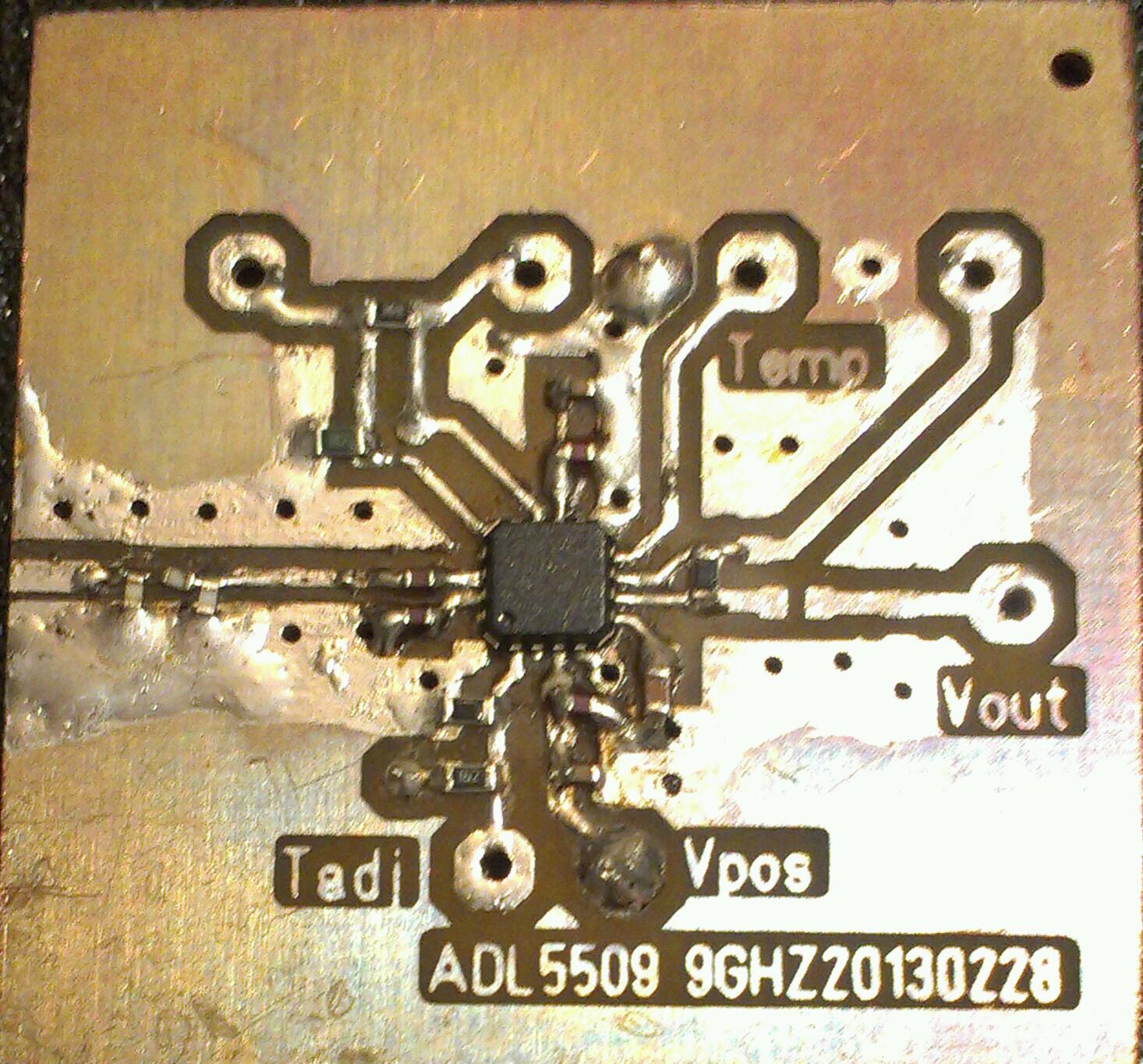
The almost completely assembled PCB. Probably not the best soldering result ever.. I had to rework the soldering of the LFCSP-16_VQ package several times, to ensure all pins made contact. Note: Ground thru-wires yet to be placed in all the holes across the PCB in the picture above. The marking "ADL5509" on the PCB is incorrect, it's really meant for a ADL5902 chip!
Measured results at 2,3GHz:
Pin      Vout     ADC 8xADC
+13dBm = 3,45V  = 691 5528
+03dBm = 2,91V  = 595 4696
-37dBm = 0,792V = 158 1271
delta:
40dB   = 2,118V =     3425
So the SLOPE: 40dB/ 2118mV = 52,95mV/dB  That's quite close to the specified 53mV/dB in de datasheet!
OFFSET: -52dBm
Another interesting Log detector IC is the ADL5519, this is a dual detector in one LFCSP-32 package.
This would be perfect to build a very nice SWR / Power meter.
I've tried to etch a PCB for this package (in 0,5mm pitch) but this appeared to be a bit too tiny. After etching, the pads were not separated/isolated from each other. I guess PCBs for such a small pitch can only be produced in PCB houses. Philippe Borghini / F5jwf has published a Power detector with this chip (see links page)
Universal PIC16F690 controller board with ADC and SPI to UART interface
This board can be used with the AD8319 or ADL5902 Log Power detector boards described above, to do A/D conversion and send the measurement sample values via UART(TTL level!) port to a PC for further processing. The PIC firmware can be loaded via an ICSP connector, which simplifies the firmware development and testing cycle. The UART port can be connected to a PC via a USB to TTL-RS232 converter board, or via a TTL to RS232 level converter to a real COM port which are rare these days.
I've written some simple firmware for the PIC in MPLAB/Hitech-C that reads 2 channels A/D (10bits with oversampling to increase measurement accuracy) and sends the ADC-data in hex values out on the UART port at 38400baud with approximately 10 samples/s. On the PC-side this data can then be read and processed to implement a Powermeter in software or do whatever you want with it.
The board can also be used as a UART to SPI interface (e.g. to program DDS or PLL chips), when suitable PIC firmware is written. 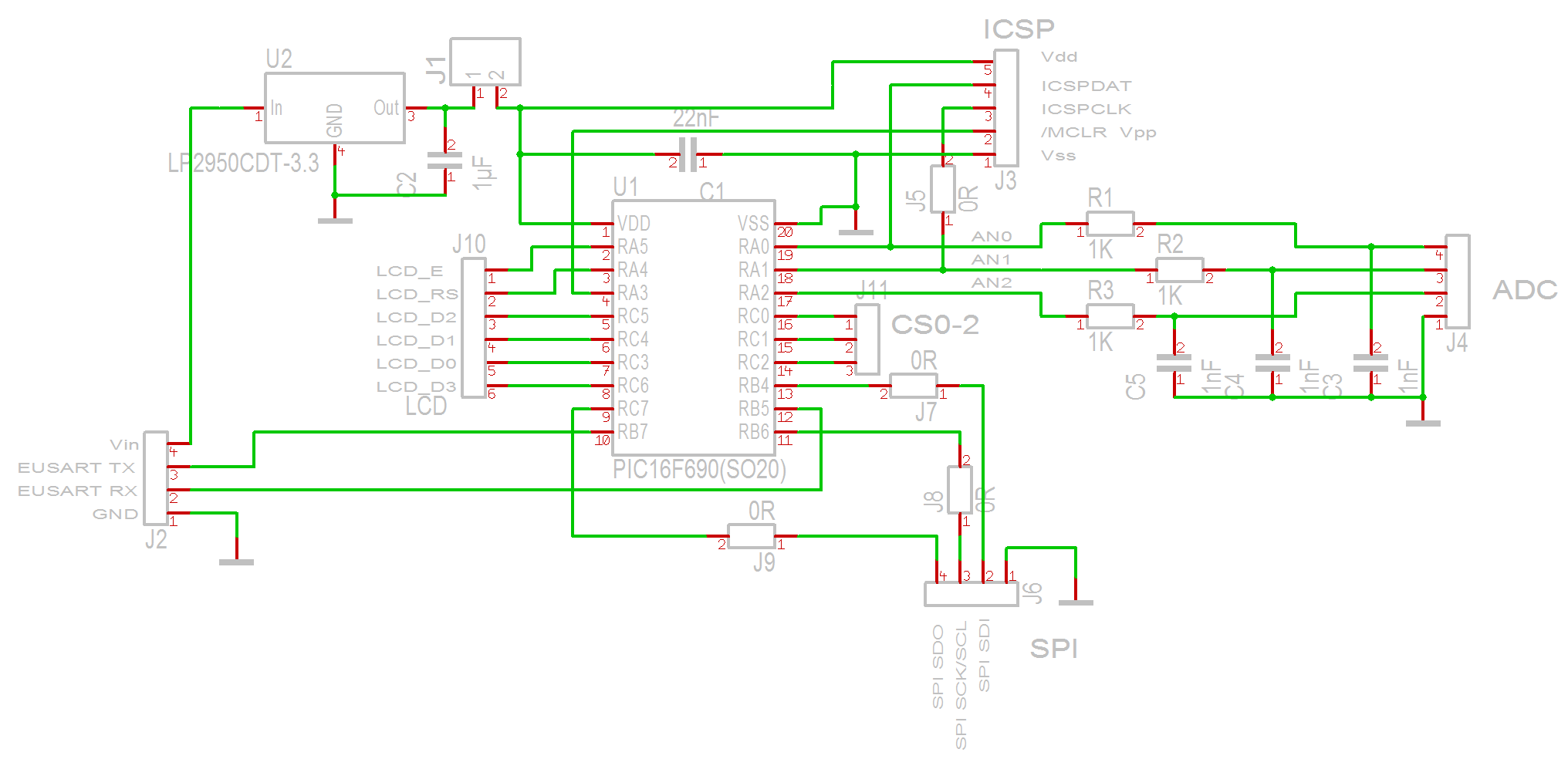
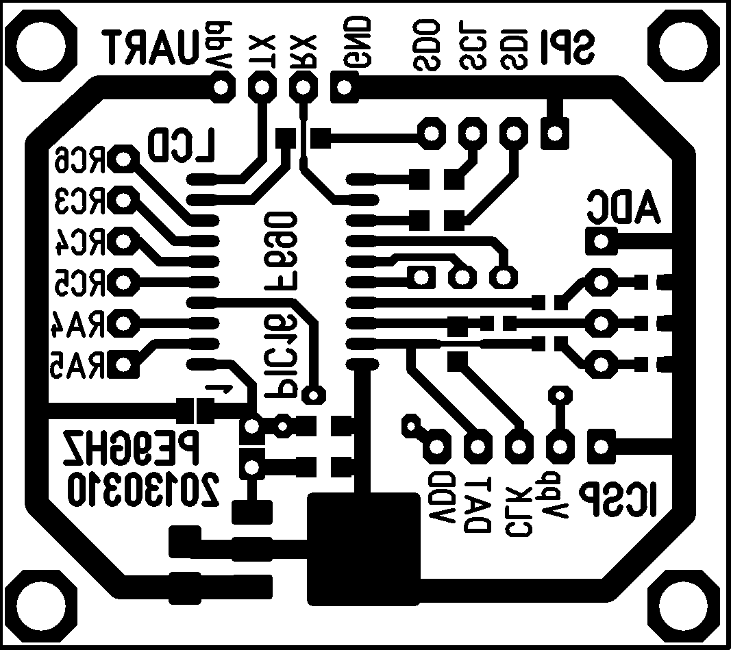
PCB dimensions: 45 x 40mm
Update 10-2013: I've stopped circuit and firmware development using the PIC16F690 in favour of the newer PIC16F886 which supports self-flash-write. This opens up the possibility to use a bootloader thus simplifying the development cycle.
A new universal controller board (with many ADC, SPI, UART ports) using the PIC16F886 is shown below
Directional coupler for 1,3-2,3GHz in Semi-rigid
Made from UT-141 semi rigid coax, with SMA(m) connectors attached to all 4 ports.
A 1/4 electrical wavelength (30mm) slit was filed in both pieces of cable. Then both cables were first tied together, with the slit facing each other, using steel wire. Then the coaxes were soldered together (see pics) ensuring the join is made HF-tight.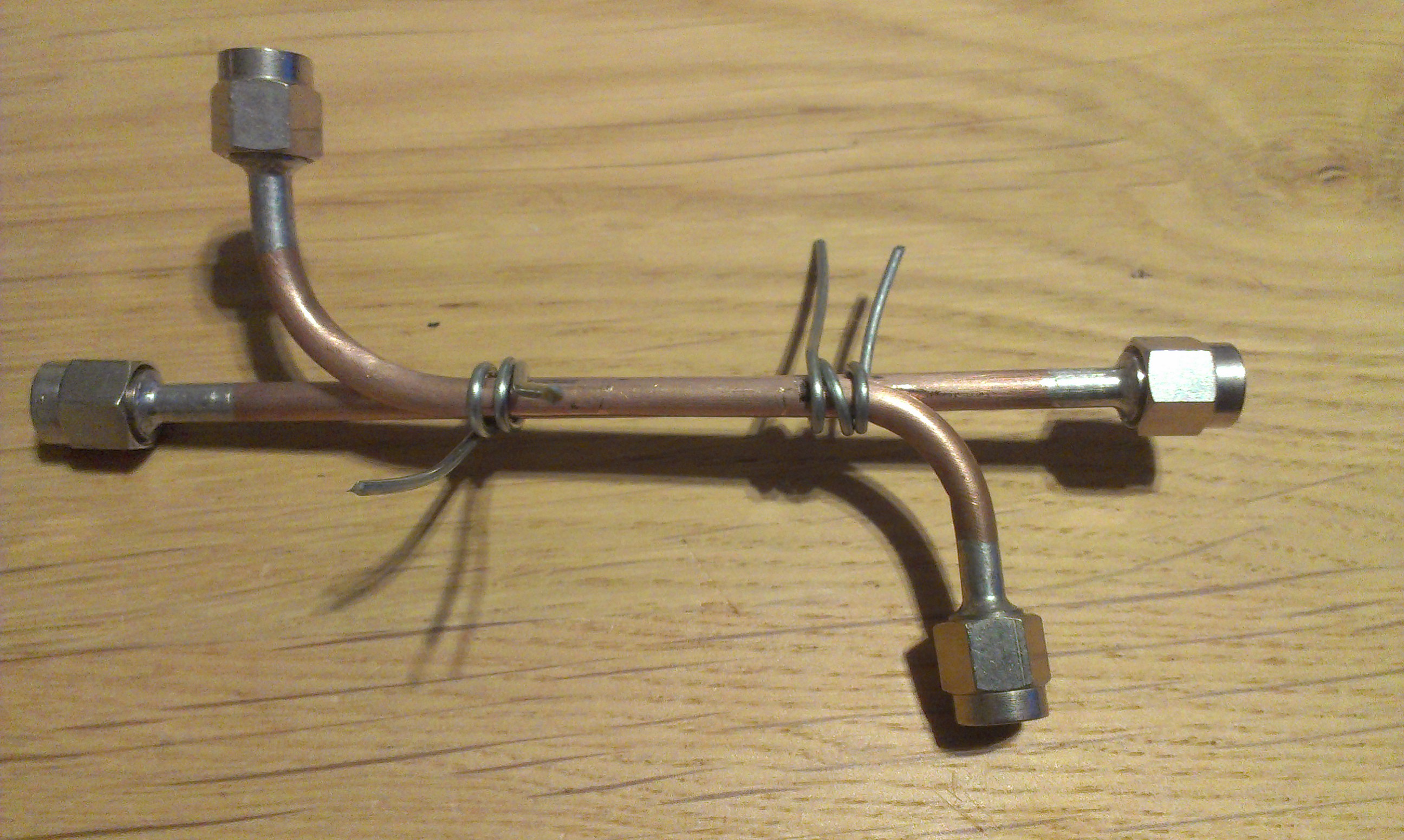
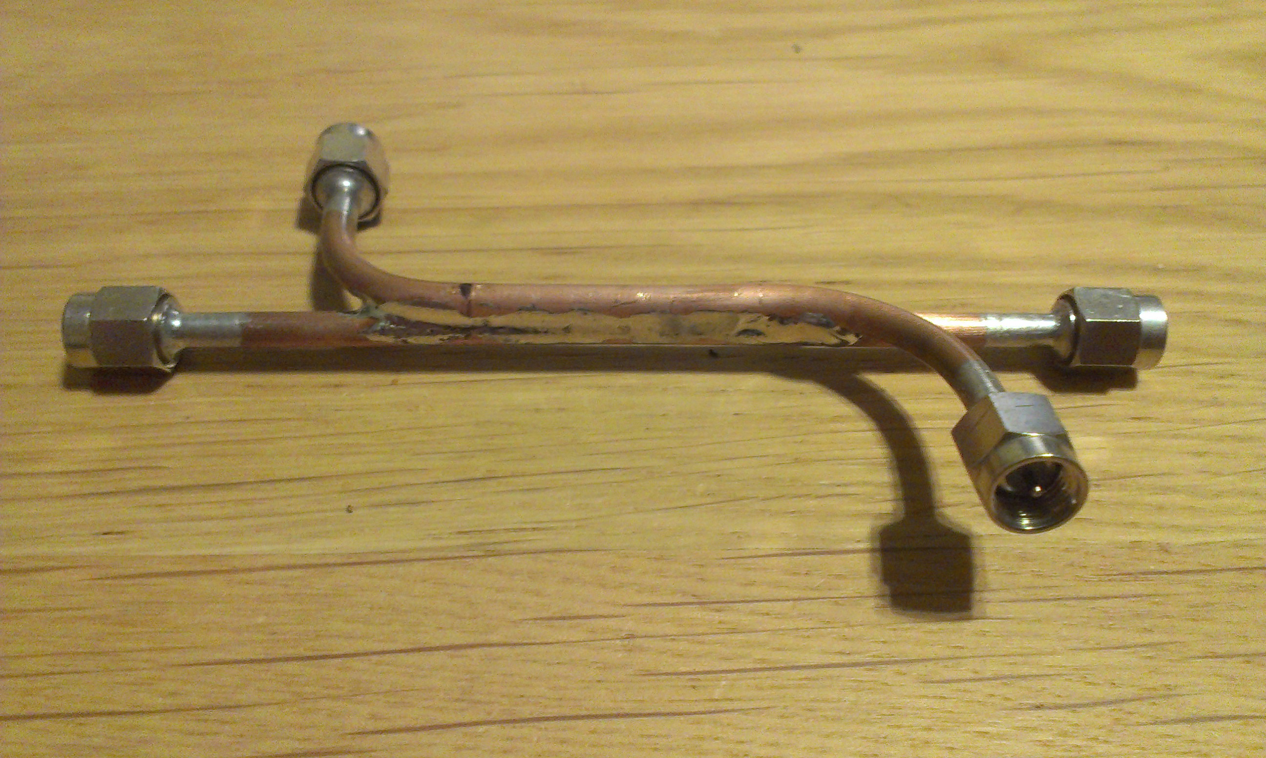
Measured Results at 2320.2MHz (13cm band):
Pin = 39.8dBm Pdir=0dBm; so Cf=-39,8dB
Pref=-23,8dBm with Narda 768-20 + extra 20dB attenuator (to present a near perfect 50Ohm match), so directivity > 23dB
Results at 1296.2MHz (23cm band):
Pin=41,8dBm Pdir=3,8dBm; so Cf=-38dB
Pref=-12,3dBm (with near perfect 50Ohm load), so directivity -16,1dB. This is not very impressive.
My conclusion is that the 30mm coupling slit is a bit on the short side for 1296MHz (the electrical quarter-wavlength in semi rigid coax is 40mm), but it works fine on 2320MHz, for which the slit is a bit too long.
So later on I'm going to construct an additional coupler with a longer slit for the 1296MHz.
Power MOSFET voltage regulator / switch
I needed a simple voltage regulator for stabilizing the 28V supply of the 40W 13cm SSPA after a rather long run of the DC cable to the outdoor transverter box. The SSPA draws 5A. Low-dropout is a must here as we don't want a lot of heat.
The circuit "MKU 2410AW DC power supply stabilizer and protection circuit recommended by DB6NT" was brought to my attention.
I designed a universal PCB that holds the circuit with a IRF4905S in D2-PAK case as MOSFET switch, this board can now be used for two purposes, depending on the compontents placed on the PCB: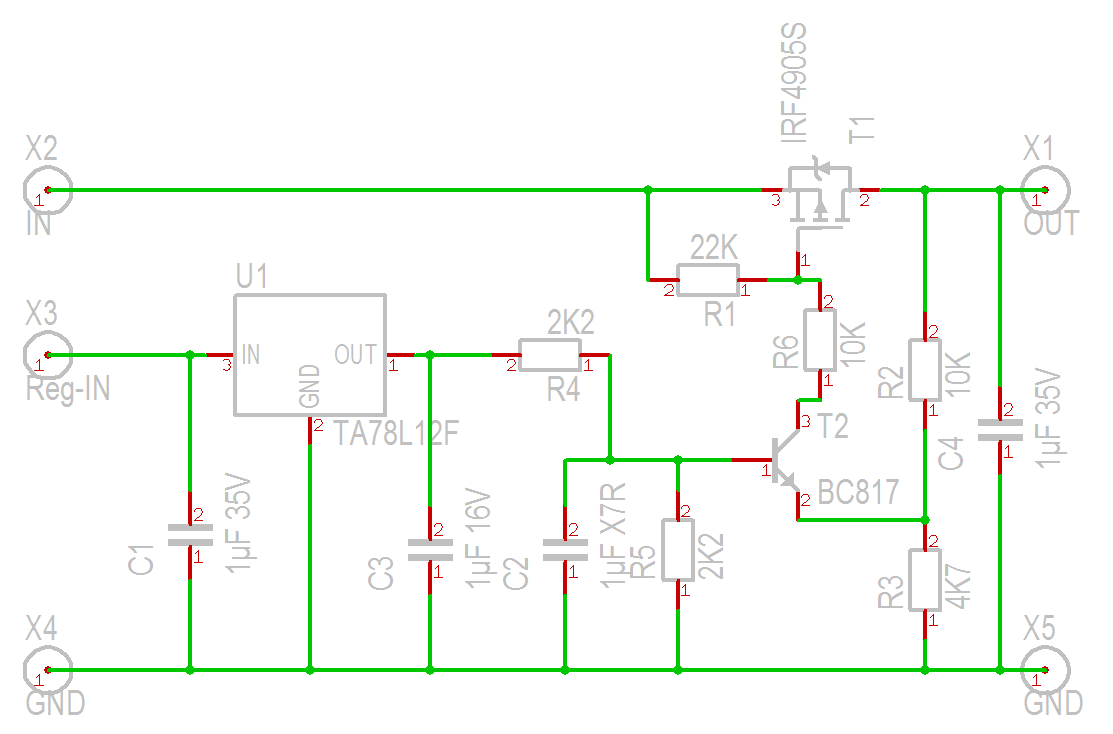
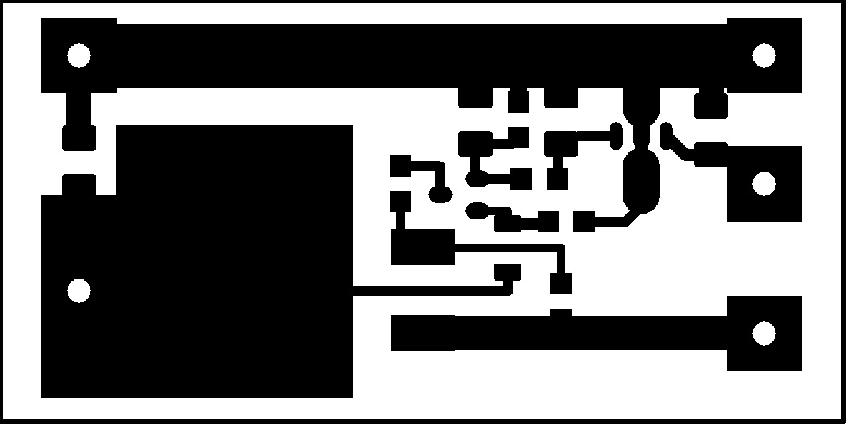
a) Voltage regulator. The required output voltage can be programmed by choosing appropriate values for the resitors R2 and R3. R6 should be a 0R jumper.
b) MOSFET power switch: By omitting the 78L12 and surrounding parts C1,C2,C3, and changing some resistor values (R6=10K, R3=0R, R2 not placed), the control input at the BC817 can be driven by a TTL level (e.g. from a sequencer) to switch the 28V Power supply line of the 40W SSPA.
Pre-Heater / Hot plate for SMD soldering with IRF4902 or IRF5305 MOSFET
My old hotplate/stirrer died (the heater element became open, so no more heating), so I had to come up with an alternative (at least for pre-heating PCB's for hot-air soldering).
This circuit with the IRF4902 or IRF5305 mosfet in TO220 can be mounted on a 75x75x5mm aluminum plate, and it can heat that plate from room temperature up to 100degrC within a minute or so, drawing 5A from a 12-13,8V DC power supply(limited by R6). A nice thing is that the Drain (Flange) of the mosfet connects to ground, so no insulating materials are needed, improving heat transfer.
Once the set temperature (R10) is reached (measured by KTY10-6 which is also mounted on the hot plate), the circuit maintains temperature while drawing only a fewhundred milliAmps.
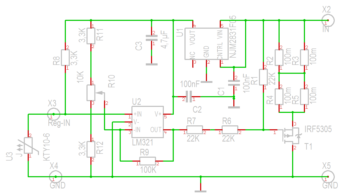
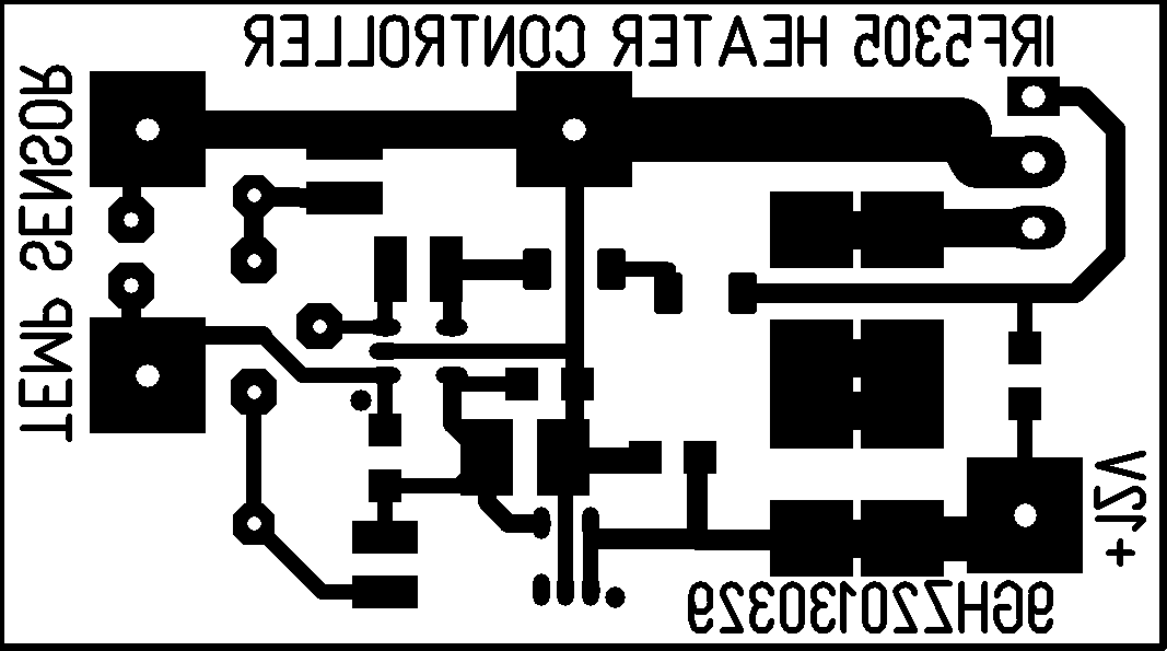
Note: There's a small error in the schematic and PCB: For a sufficient output swing to drive the MOSFET, the V+ pin of U2, LM321 opamp should be connected to +12V in, not to the +5V output of U1 NJM2831F05 regulator. To fix, cut the trace near U2 and place a wire-jumper to the +12V trace.
2,3GHz loop feed for 120cm dish with f/D=0,53
I'm currently using a "24dBi Wifi Grid antenna" for my 13cm operations at Radioclub PI4Z.
To improve my antenna setup, I intend to use a 120cm prime focus mesh dish which was donated by someone and is currently unused.
This 120cm dish (with f/D=0.535) was formerly used for 1,6GHz weather satelite reception and no feed was included.
So I had to make a feed for it. It was suggested to make a ring loop feed (as published by DL4MEA for example). The loop feed is relatively simple to construct, has a relatively low reflector blockage, and is suitable for dishes with f/D around 0.4 - 0.5. This one has a lambda/2 (65mm) reflector diameter.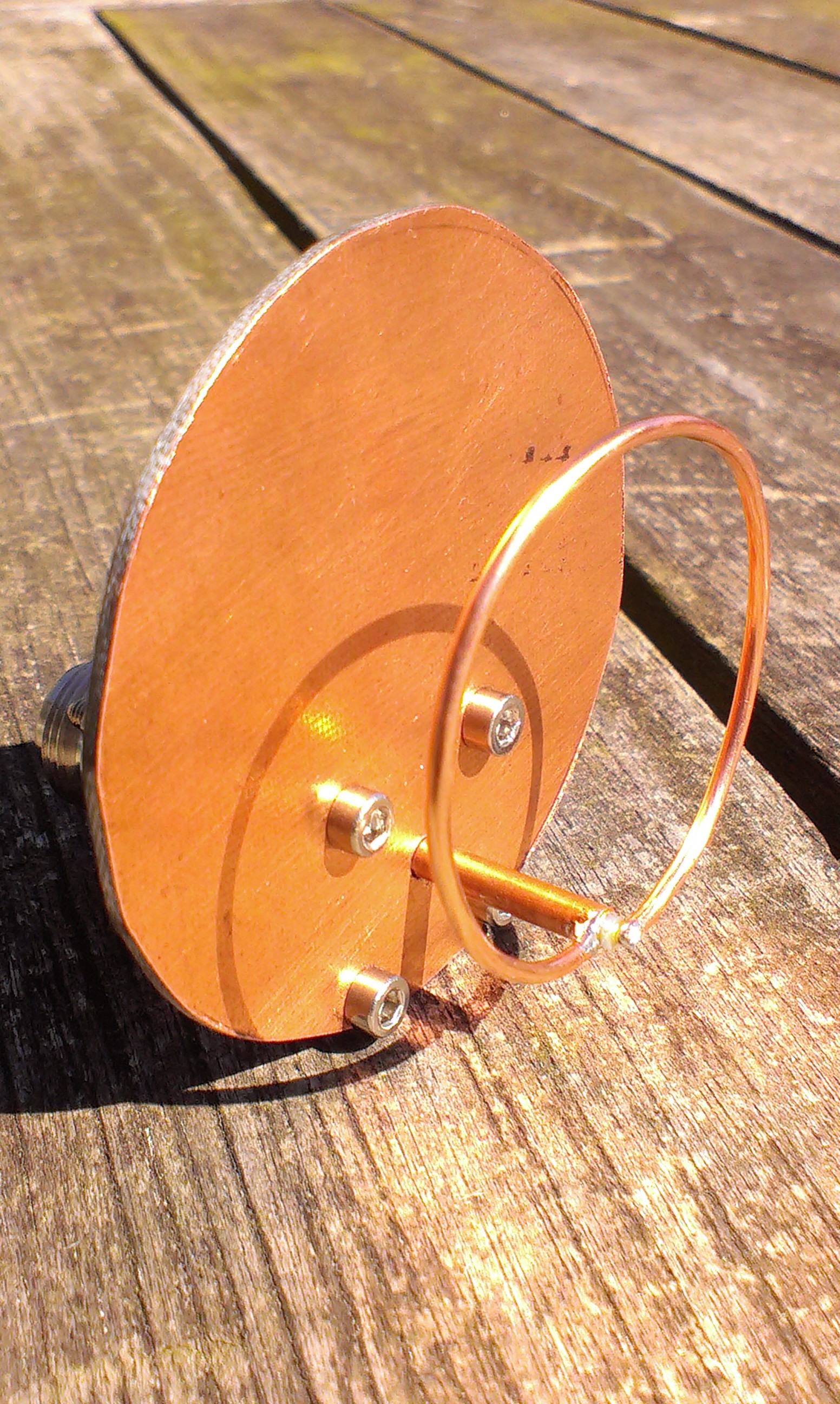
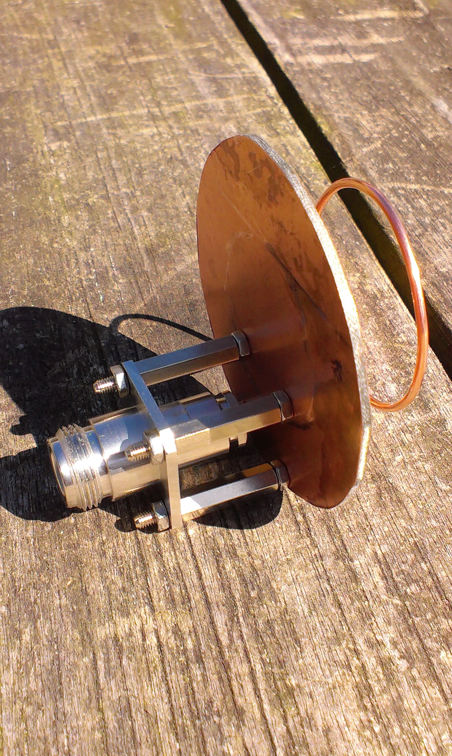
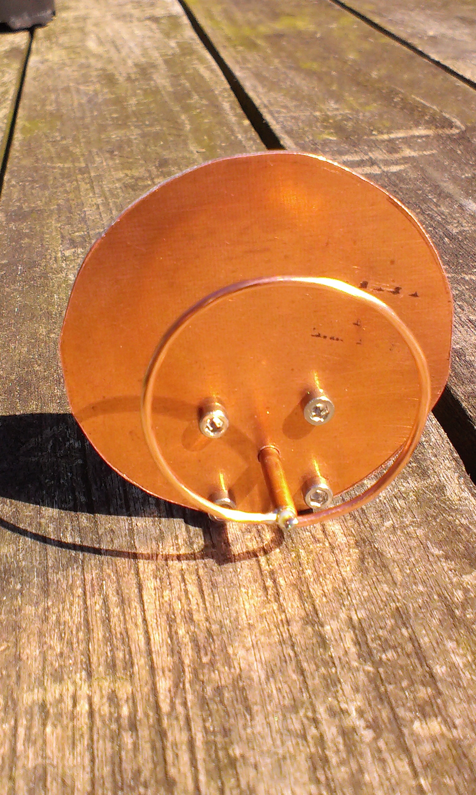 Some pictures of the loop feed.
The loop was made of 2,5mm2 solid copper wire. After adjusting the loop - reflector distance to 1/8 lambda (16mm), a free space return loss of > 20dB at 2320MHz was obtained. But mounted in the focal-point of the dish, the RL became much worse and the resonance frequency shifted to 2352MHz where RL was still very good. By decreasing the distance between loop and reflector, the RL at 2320MHz could be improved to an acceptable level but I was not satisfied with it. Thus, a new loop was made with a 127mm long 6mm2 solid copper wire, which was first silver-plated then bent in a circle with D=39mm. Next will it will be soldered to the feed, replacing the old loop, then the resonance frequency and RL will be measured again. Probably length of the loop will need to be shortened (mm by mm) to get it to work perfectly at 2320MHz. I'm using a Comtech 13cm ATV exciter with IK8UIF LCD interface + a small 1Watt PA (works from 2,25 to 2,5GHz) as a test signal source for alignment.
The feed F/B ratio can probably be improved by enlarging the reflector diameter and adding a collar, as described in Dubus Enhanced Loop Feed (local copy here). This leaves room for some experimenting in the future.
Universal PIC16F886 controller board with 10ch ADC, digital IOs, SPI, PWM and UART interface
This universal controller board with PIC16F886 was developed for use as a control and measurement system in (microwave) transverters and other equipment.
With the proper sensors, 10 analog inputs can be utilised to sample e.g. Forward and Reflected Power, Current and Voltage monitoring, temperature etc. Digital IO ports can be used to monitor PLL lock state, PTT state. I2C or SPI interface can be used to connect monitoring devices. PWM outputs are present to drive cooling FANs (indirectly).
The UART port can be used to interface to a RS485 bus. This enables using more measurement monitoring and other devices on the same bus and a central monitoring system. Each controller board can be setup with 1 or 2 addresses, with up to 15 unique devices on the bus. A protocol compatible with the Icom CI-V protocol will be used, so eventually other CI-V enabled radio's could be connected to the same bus. To avoid problems with ground-loops with common ground and high currents, an Opto-Isolated RS485 interface separates the (outdoor) transverter equipment from the RS485 bus.
Interfacing to a PC can be done using a USB-to-RS485 adapter or even with a LAN-to-RS485 adapter.
Firmware for the PIC is currently under development by Bart PE1PFW and me. The PIC can be programmed using ICSP (initially) or with a (TinyBLD) bootloader using the UART port.
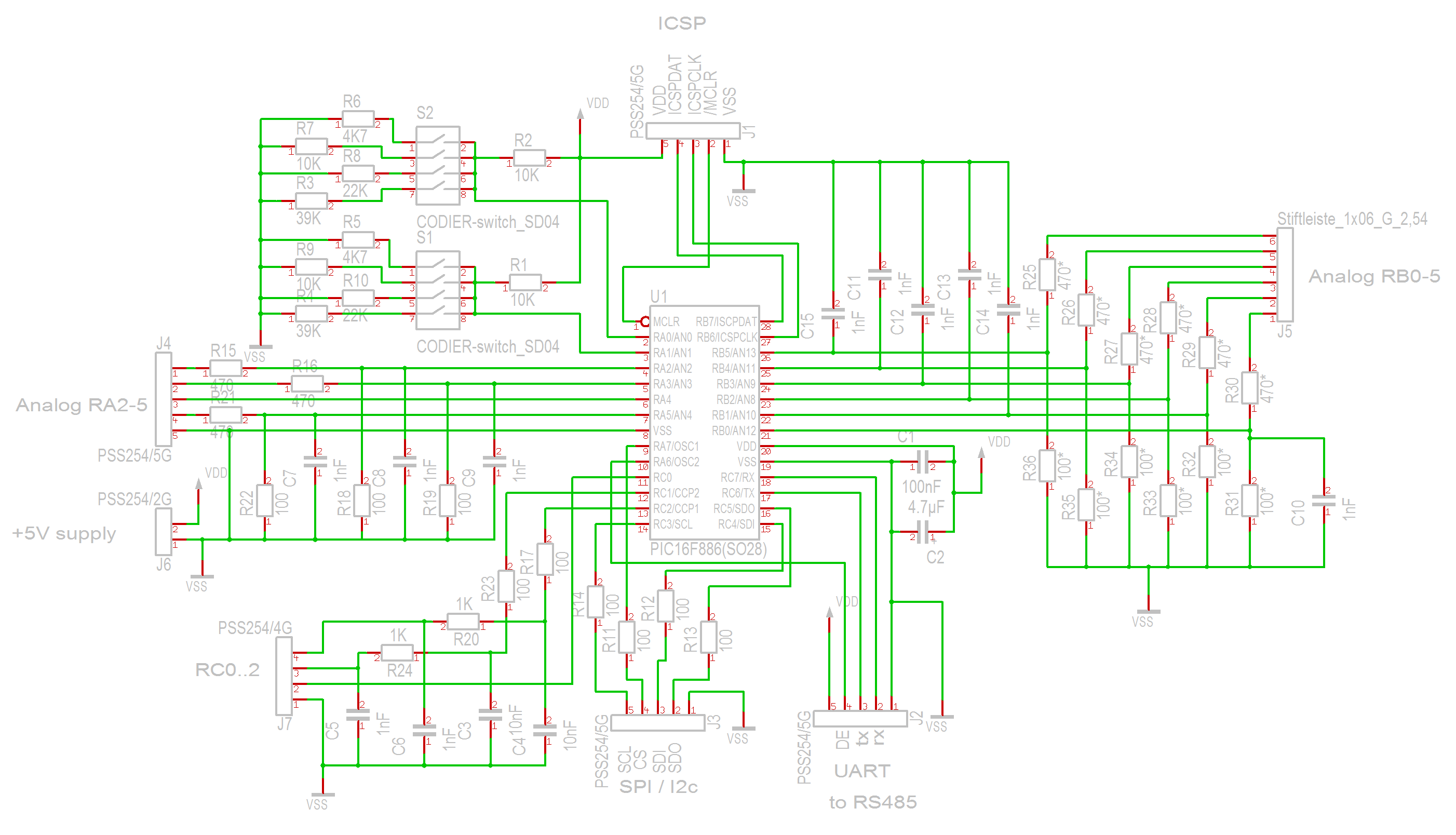 Schematic diagram
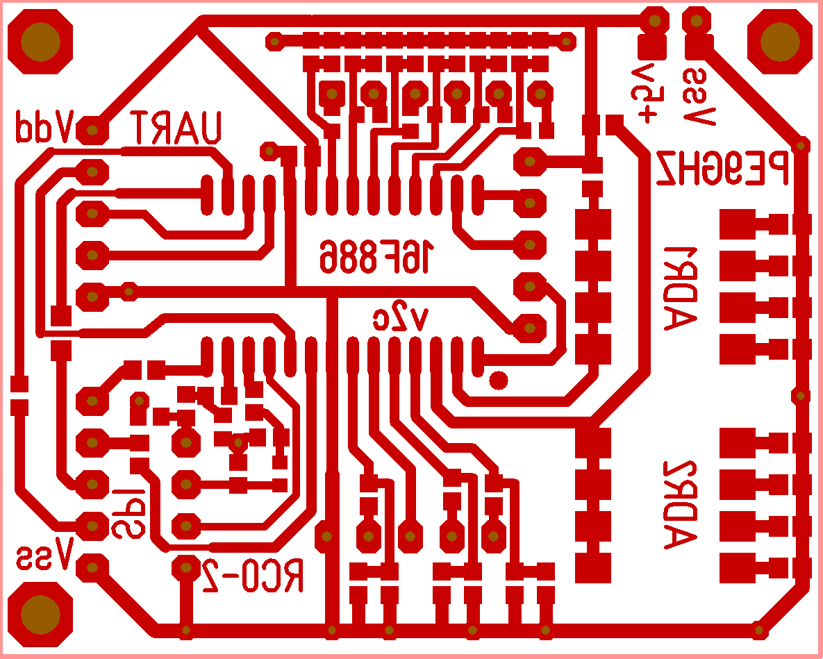 PCB v2c for Universal PIC16F886 controller
Universal PIC16F886 controller Firmware: under development.
- Test version v1.64spi (UART-to-SPI): download hexfile
This firmware implements simple communication from UART to SPI port (talk to SPI-enabled chips like DDS or PLL's). Commands: E (enable Latch/CS) D (disable Latch/CS) S (send byte, following next 2 chars are the byte to send in hexadecimal) I (identifies firmware version) R (read all ADC channel values).
UART speed is set to 38400-8-N-1, SPI port is set to SPI Master mode, clock = FOSC/64, Clock polarity select: idle state is high level. The PIC16F886 is set to HSINTOSC at 8MHz.
PC software: under development.
Page modified by Eddy on 2024-05-17
Previous page: Wavelab24GHz transverter
Next page: For Sale