10GHz-SSPA
10GHz Solid State Power Amplifier project
For 2x FLM1011-4 or FLM1011-8 in final stage
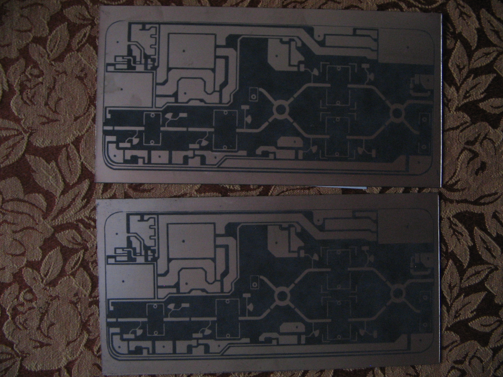
Raw PCB material RO5870-0,5mm-17µCU (180x90mm) with photoresist, was obtained from DC3XY.
The PCB was designed and etched by Michael DL1YMK "How to get QRV on 10GHZ EME in a portable way" Sweden EME 2013 presentation and Cheap solid state power on 10GHz
To get an idea of the component layout, this is how the PA by DL1YMK looks like (picture extracted from the Schweden presentation):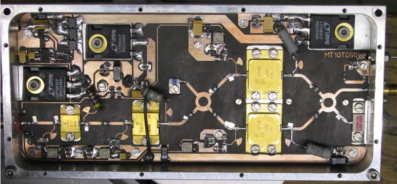
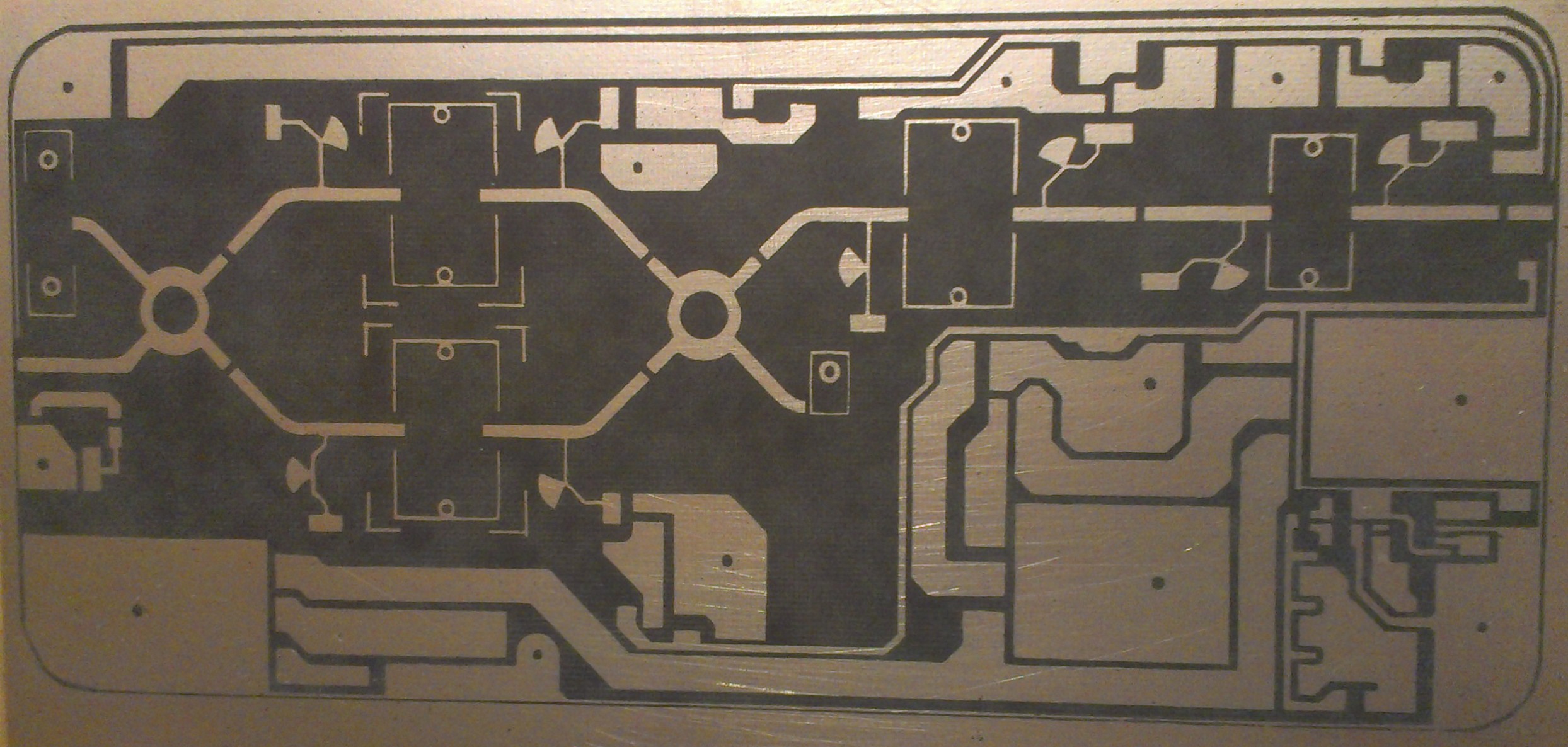
PCB dimensions 76 x 168,5mm
2 different versions of the amplifier will be built, one by Bart PE1PFW and one by me Eddy PE9GHZ.
The PE1PFW version will use: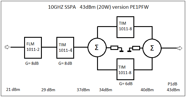
Device arrangement: FLM1011-2, TIM1011-4, 2xTIM1011-8 and anticipated Pout(1dB)=43dBm with Pin=21dBm
The PE9GHZ version will use: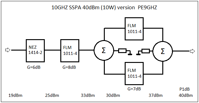
Device arrangement: A NEZ1414-2 or FLM1011-4 as the 1st stage, then FLM1011-4, 2xFLM1011-4 and anticipated Pout(1dB)=40dBm with Pin=19dBm with 1414-2 or Pin=17dBm when a FLM1011-4 is used as 1st stage.
Aluminum casings for both versions were milled by my collegue Ronald on his DIY CNC machine. Many thanks, Ronald !
The depth of the cut-outs/pockets for the 2x 10¹¹-8 FETS (13,1 x 23 x 2,55-0,5mm) are different from the 3x 10¹¹-4 version (10,2 x 18 x 1,8-0,5mm) !
Dimensions of the casings 180x90x20mm.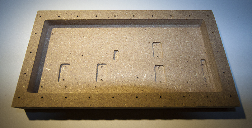 Prototype of casing in MDF.
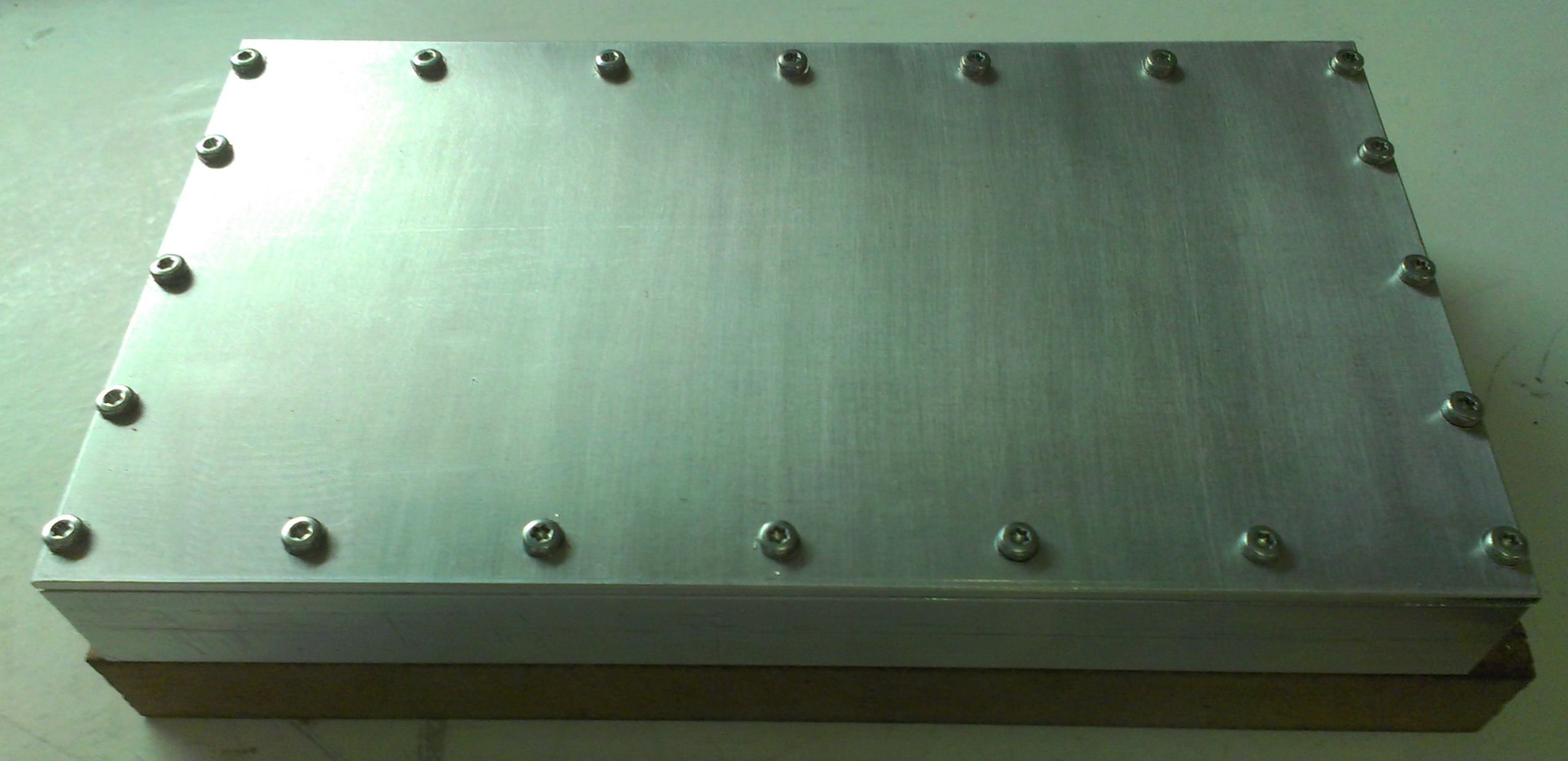 Finished milled casing with lid
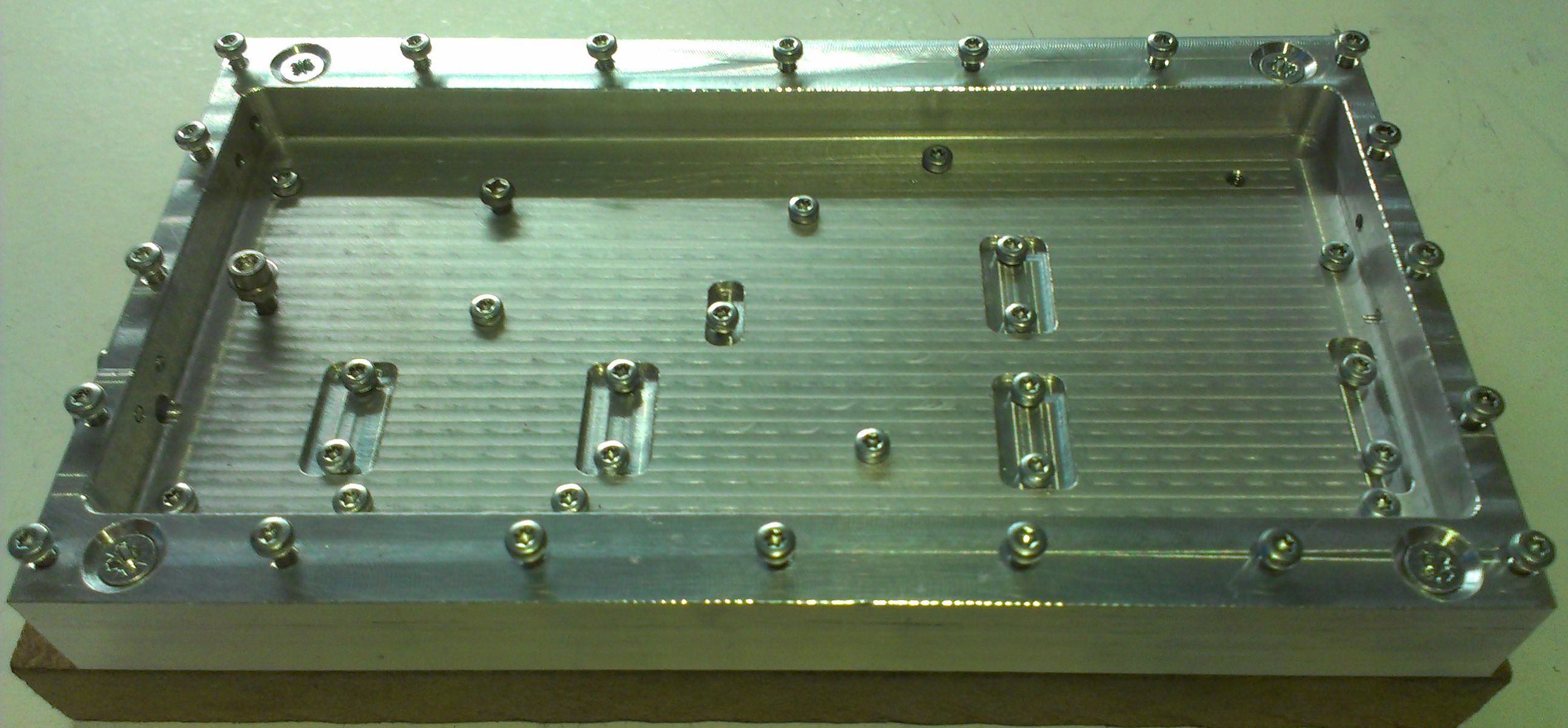 Inside milled casing, all screws fitted.
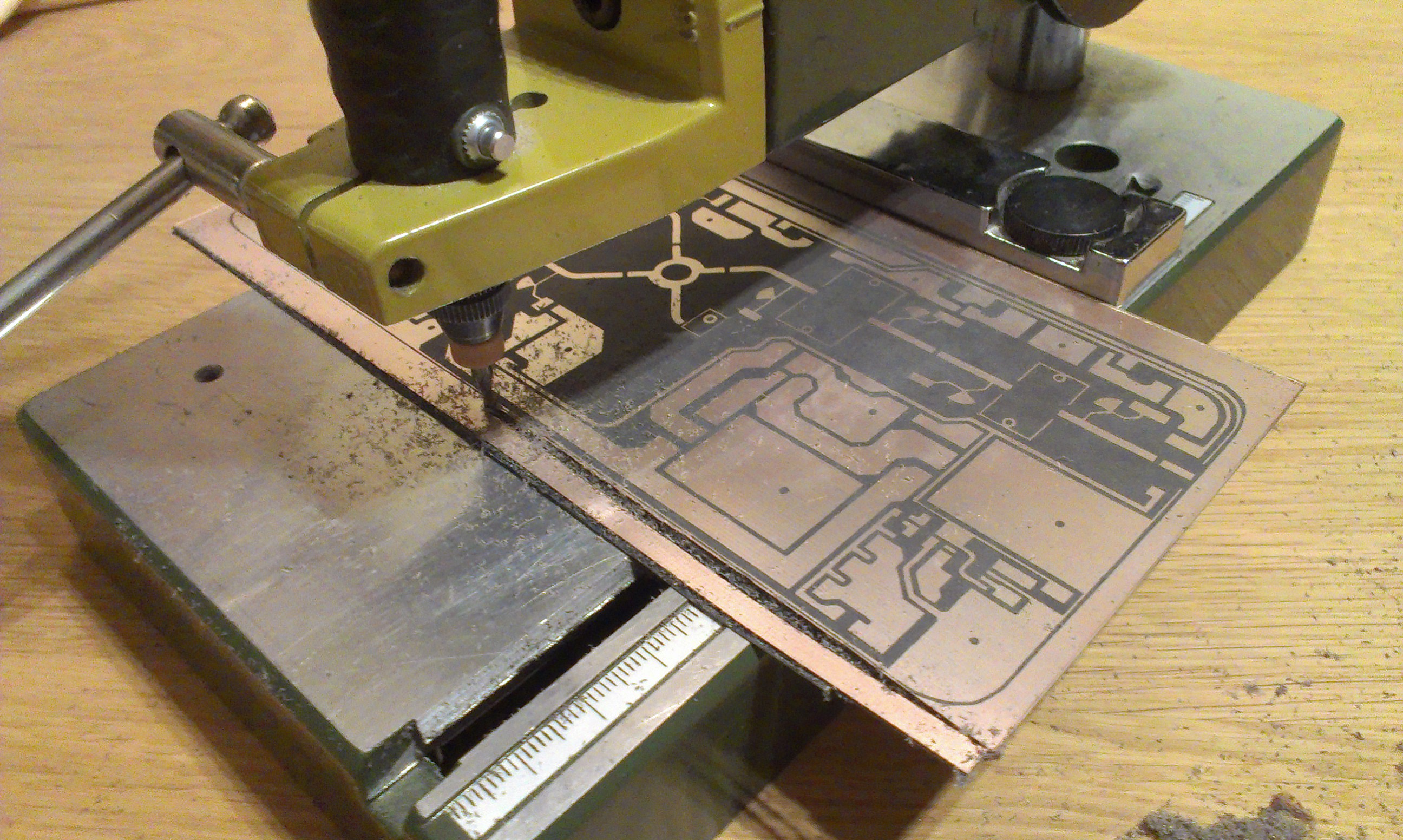
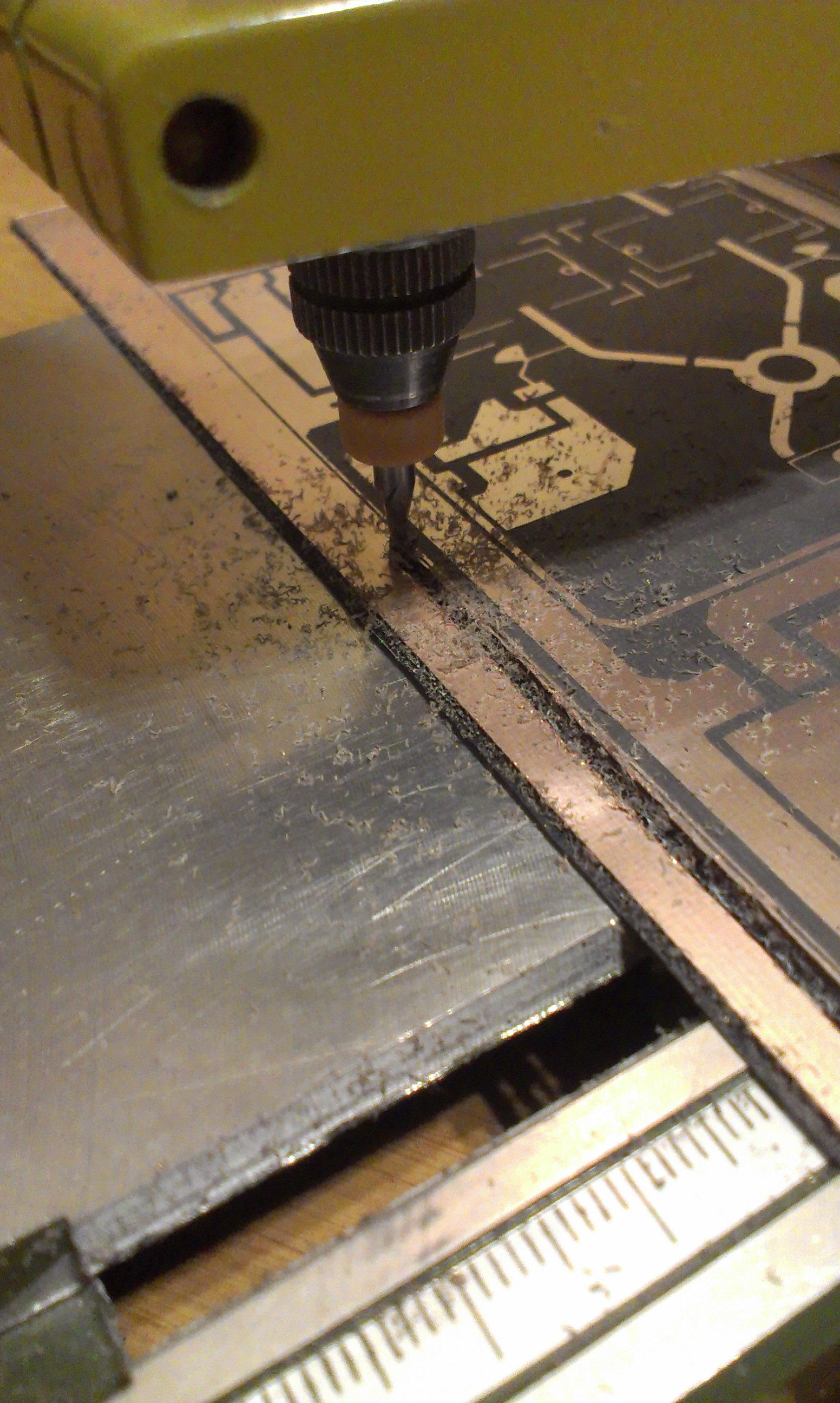 Preparing the PCB
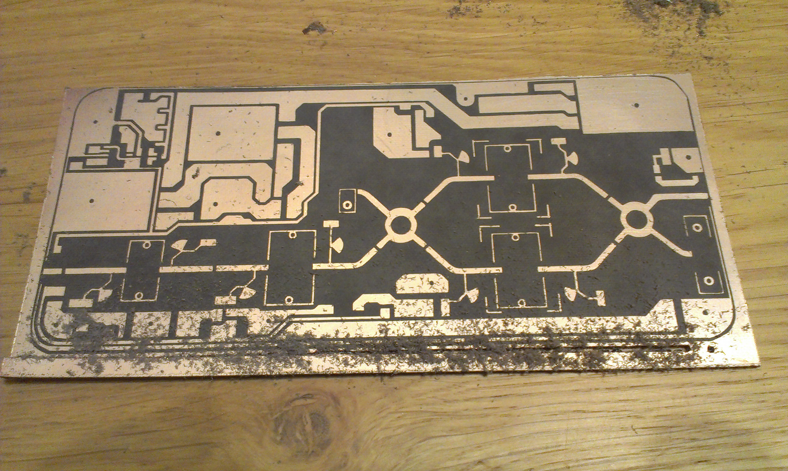
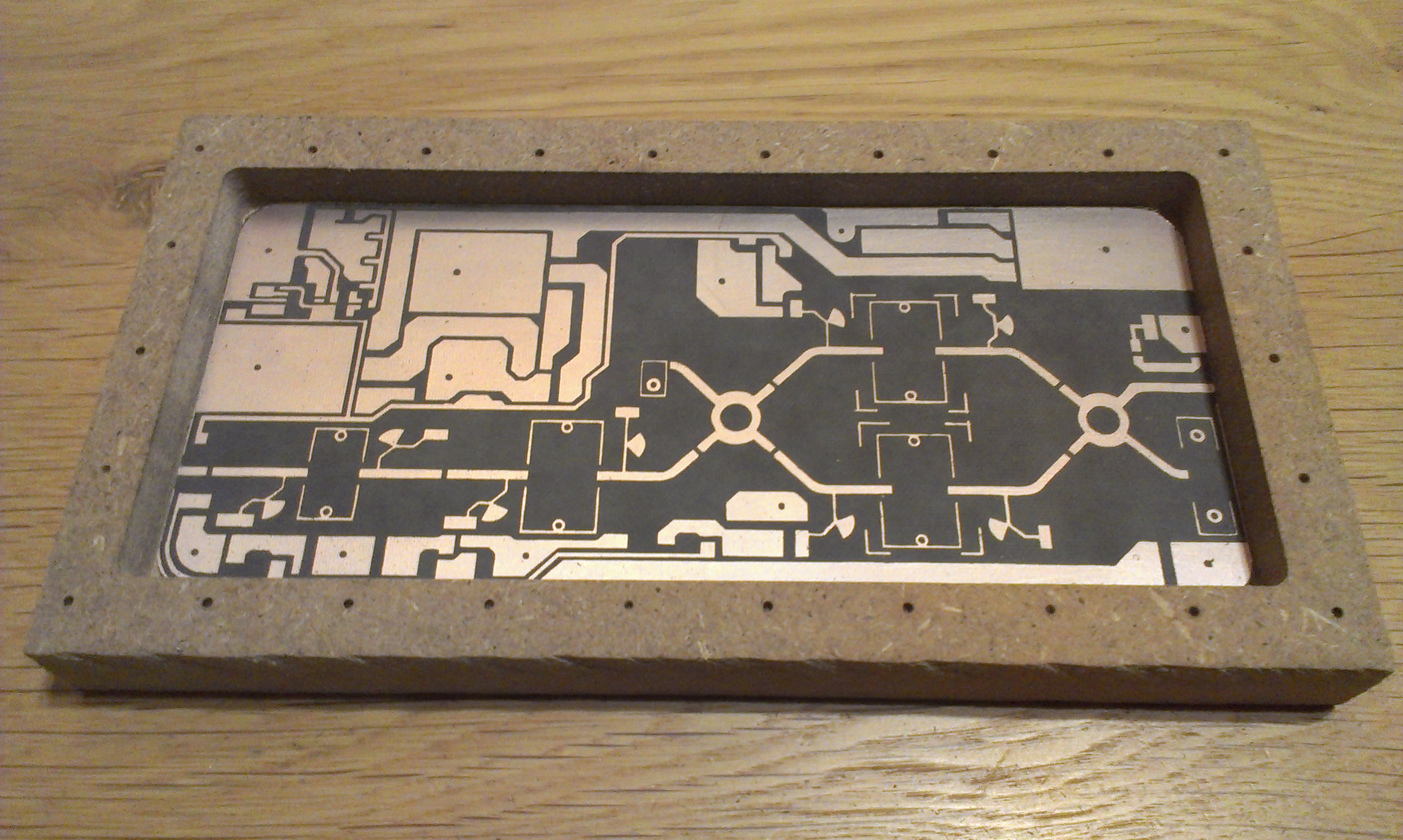
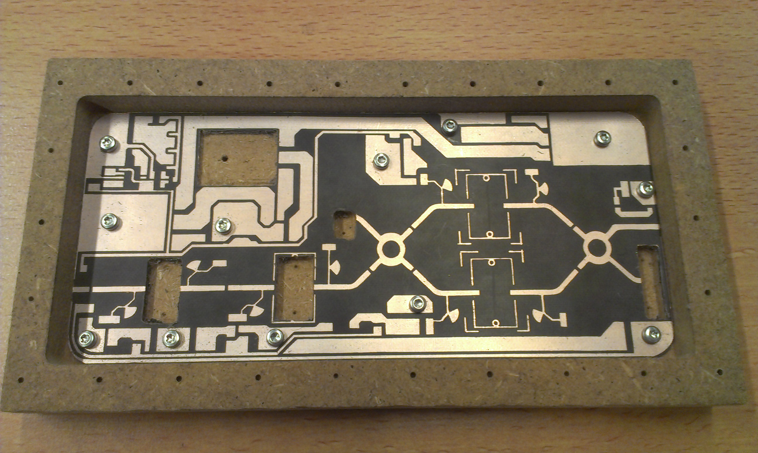
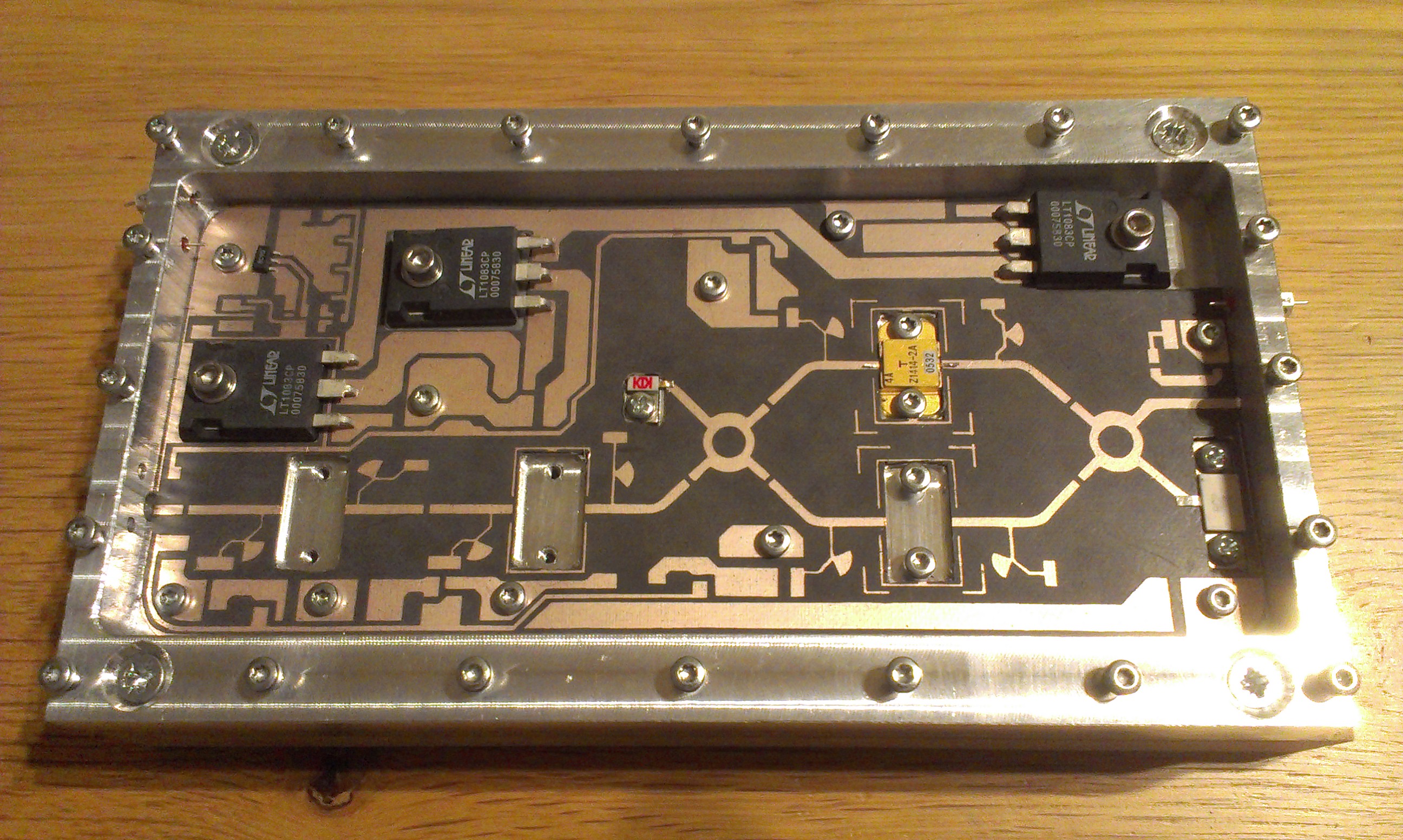 PCB fits perfectly in the alu case.
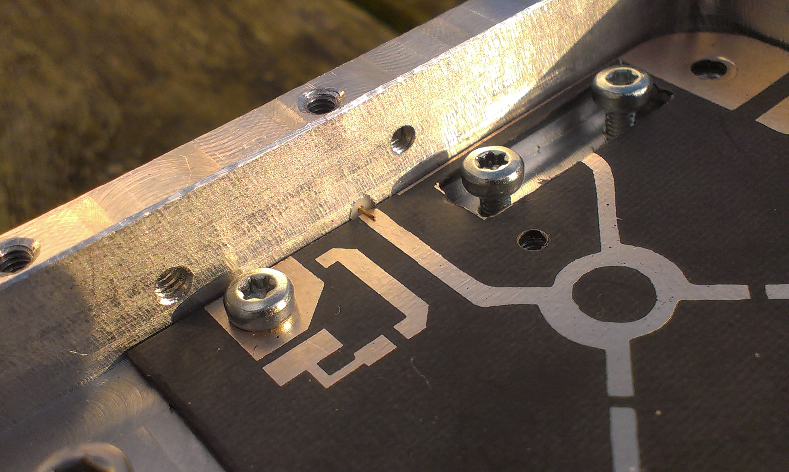 Output to very thin (0,2mm) precision SMA centre pin.
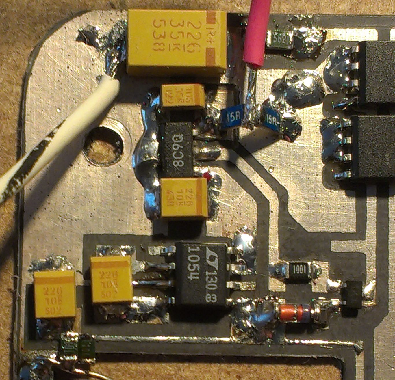 Negative bias and DC switching circuit built in upper left corner of PCB. Note: An ICL7660 is unable to deliver enough bias current, so a LT1054 was used instead. Pin7 was lifted from the board and left unconnected, as the layout was designed for a MAX861. To facilitate PTT action (and shut down the PA when not transmittting), the input pad of the 78L05A was separated from the main supply. It will be connected to a 12V-active PTT line in the transverter system.
Update march 2014: I've built my amplifier and now I'm trying to align / flake for max output power. So far not very succesful, after many hours of flaking and one fried FLM1011 later, only 7W obtained with 100mW in. Very disappointing... :-( Still trying to figure out what is wrong. FETs biased at resp. 600mA, 1000mA, 1000mA, 1000mA.
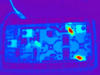
However, Bart PE1PFW has built and finished his version and he obtained 22W output easily with 150mW input.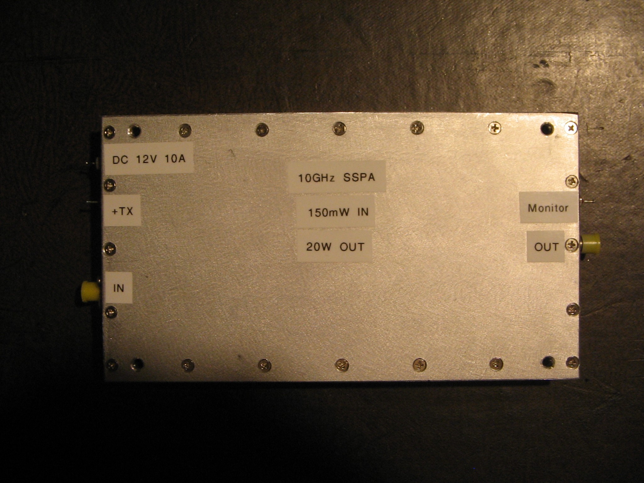
Drawing of the Alu casing by DL1YMK: Alubox_MT_10TD50WA.PDF
Just for reference here is a link to some Kuhne Electronic PA casing: 10GHz-25W 10GHz-8W
SMA connectors on output: 2-hole flange. Flange length: 16,0mm width 6,0mm, thickness 1,65mm. Holes: 2,6mm at 6,1mm from center. ptfe isolation diameter=2,14mm length=5mm, round center pin diameter=0,2mm
Input: 4-hole flange. ptfe isolation diameter=4,05mm length=5mm, round center terminal diameter=1,0mm
Some datasheets of the components used (local mirror):
FLM1011-4 TIM1011-2 TIM1011-4 TIM1011-8
Spectrum Control 1250-003 8-32 UNC Feedthough filters see page 78 of pdf
Excelics EPA018A-70 replaces the MGF1302 FETs in the output stages of my 10GHz transverter to increase output from +10dBm to +19dBm.
Page modified by Eddy on 2014-03-20
Previous page: 12Vto24Vdc Converter
Next page: Wavelab24GHz transverter
