1,3+ 5,7 + 10 + 24GHz Personal Beacons PE9GHZ/B
based on my project: Small Beacon transmitters PLL-locked to a (10MHz) Frequency Standard.
Note: latest up-to-date info is near the bottom of this page.
Update: 2016-10-02 Now we added a 23cm (1296MHz) and 6cm (5760MHz) beacon to the setup.
The 10GHz beacon consists of:
- A PLL-VCO module (as described on this page) with output on 1296.102MHz, but slightly modified (the AG602-89 mmic is replaced with a sky65017 (sot89) mmic, which can make a few more dBms output required to drive the next stage):
- A x8 multiplier module, consisting of Hittite HMC188MS8, HMC189AMS8passive frequency doublers and a HMC368LP4 active x2 multiplier and some buffer/gain block mmic. Input: +13 to +14dBm at 1.29GHz, for +15dBm output power on 10GHz.
- Isolator
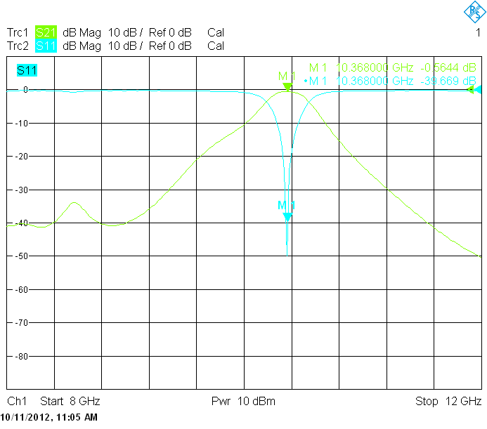
- A waveguide band-pass filter for 10368MHz, to filter unwanted spurious from the x8 Multiplier. Insertion loss: 0.6dB. Bandwidth 350MHz. Return Loss > 30dB (measurement data near bottom of page).
- A 10GHz Solid state Power Amplifier module, input +10dBm, output +30dBm. (Unfortunately, one of the output devices died due to a brief short between +10V and -5V bias supply voltages. Now only a maximum of +26dBm or 400mW output can be obtained). I hope this is still sufficient output for the beacon to be received in the surrounding area.
- Power-supply for the SSPA, with automatic on/off control of the +10V output by the status of the negative 5V bias and by the PLL-lock status signal from the PLL-VCO, so the beacon's PA-module will be shut-down if the PLL-VCO is unlocked or negative 5V fails (to protect the PA).
- Isolator
- Transition from SMA - WR90 waveguide.
- 2x18 slots Waveguide Slot antenna.
- CW-ID / Callsign generator: a PIC10F20x with a small program written in MPASM by Bart PE1PFW. The module has a control-output to turn on the beacon after a poweron_delay of 10 minutes, which is the minimum time needed for the DOCXO reference to reach a stable output frequency.
- Remote-controller for switching the beacon on / off by the beacon keeper(s).
- Extra: A Morion MV-89A 10MHz DOCXO (double-oven controlled xtal oscillator) reference.
- A Mini-Circuits ZFSC-2 splitter to split the 10MHz reference signal for the 10GHz and 24GHz PLL-VCO's.
Our intention is to build all of this in a IP66 waterproof (Fibox) ABS case, and put the beacon up in the antenna tower at our Radio Club PI4Z for at least an extended testing period.
Also, Bart PE1PFW has prepared the modules / building blocks for a 24GHz beacon, that we will build into the same case, so the result is a combined 10GHz + 24GHz beacon.
The 24GHz beacon consists of these modules:
- A PLL-VCO module, with a ZCOMM vco, output on 1503,0509MHz.
- A x8 multiplier (same type as the multiplier used in 10GHz beacon), output +15dBm at 12GHz.
- Isolator, a 12GHz cavity bandpass filter, Isolator, 12GHz cavity bandpass filter.
- x2 mulitplier / final stage, input: +4dBm at 12GHz, output: 23dBm at 24GHz into WR-42.
- Isolator in WR-42
- 2x8 slot Waveguide Slot antenna in WR-42 with "wings" made of WR-42 on both sides.
(Planned) Output frequency of 10GHz beacon: 10368,814998 mark / 10368,81415 space
Beaconspot entry here
(Planned) Output frequency of 24GHz beacon: 24048,815038 mark / 24048,81355 space
Beaconspot entry here
- After rigorous testing, we plan to host the beacon at a suitable high location somewhere in our area, possibly on the former PI3GOE repeater site in Zierikzee.
- Below are some photos of the beacon modules / PCBs:
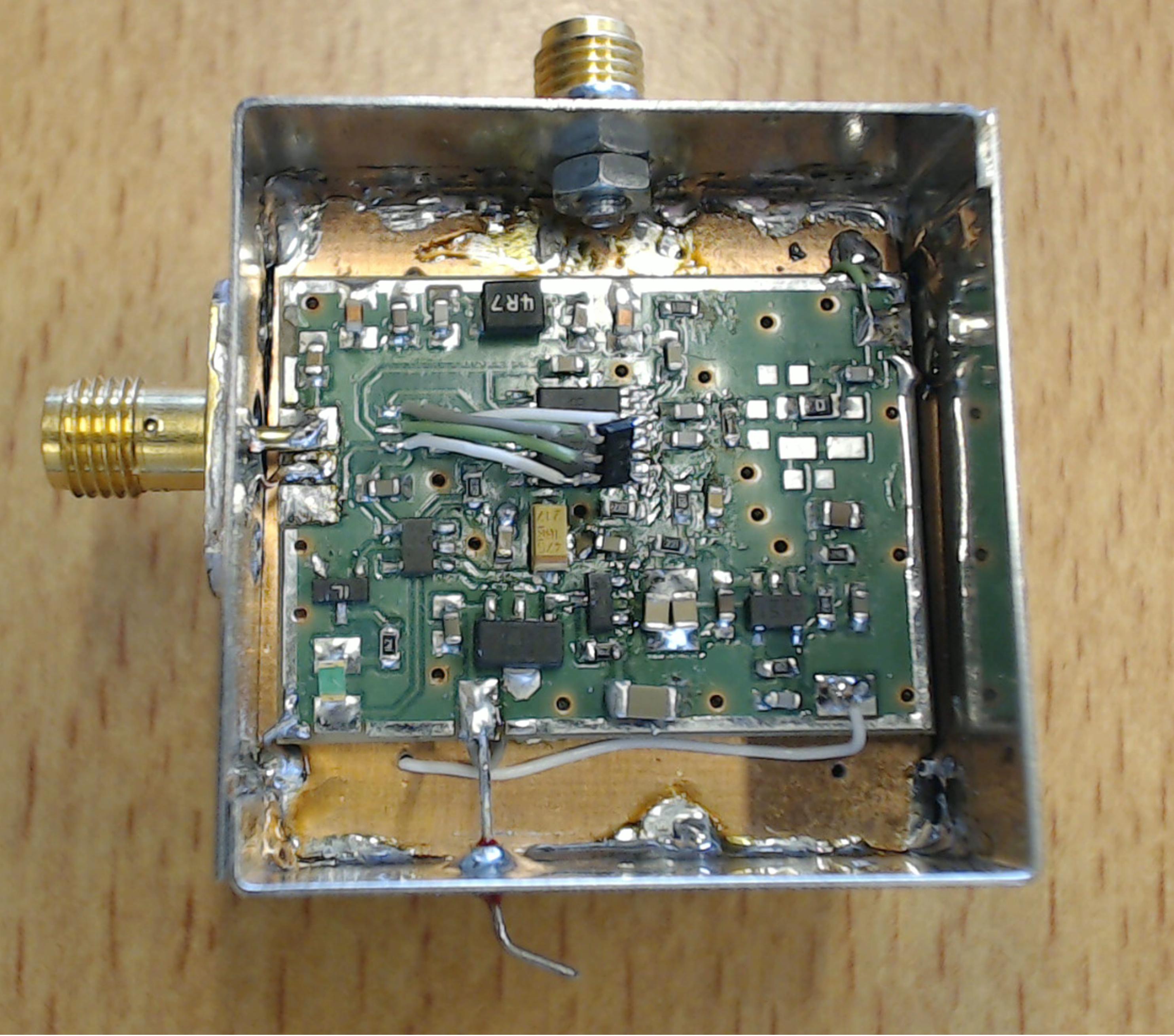 The PLL PCB designed by Bart
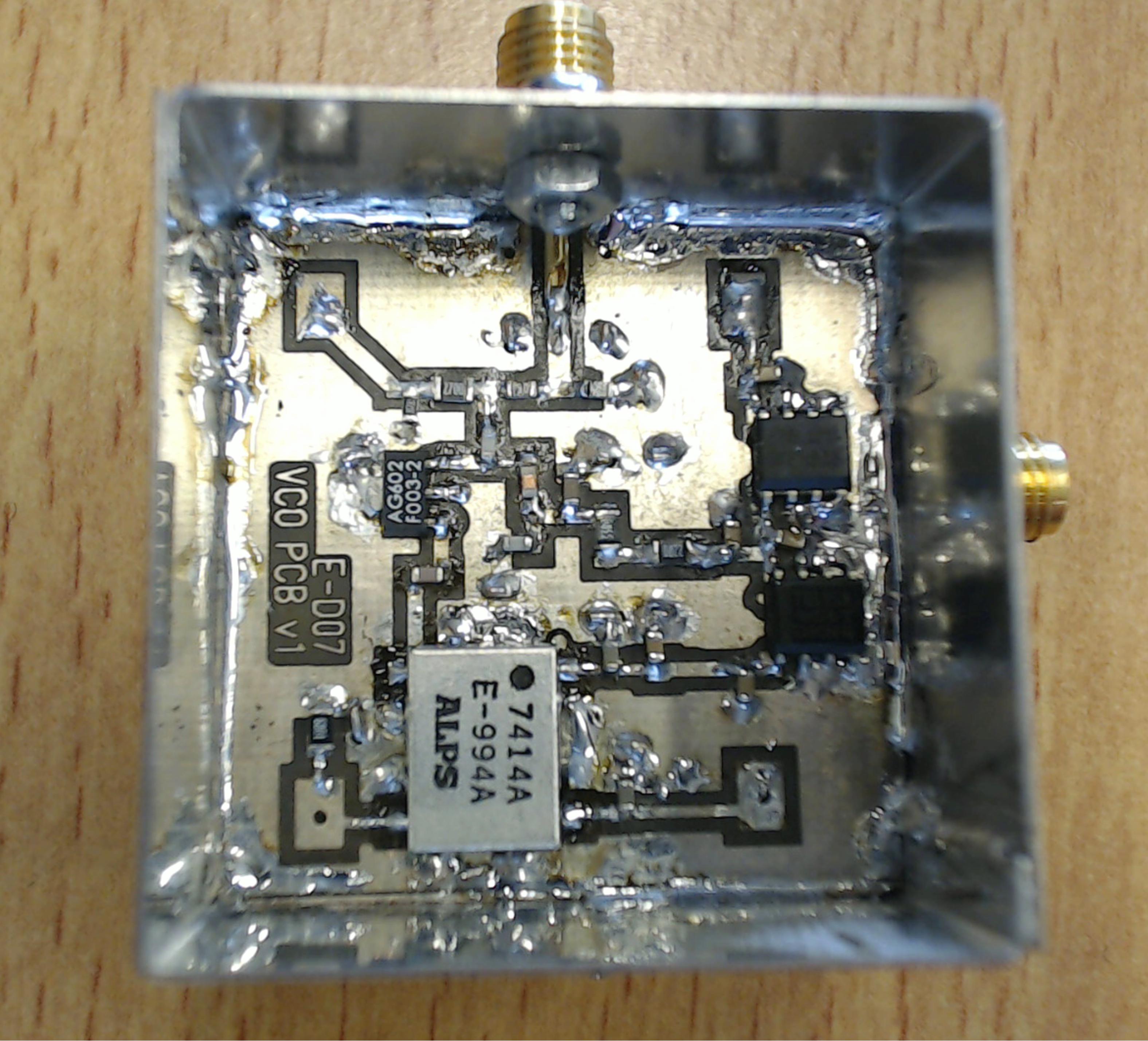 The 1296MHz VCO
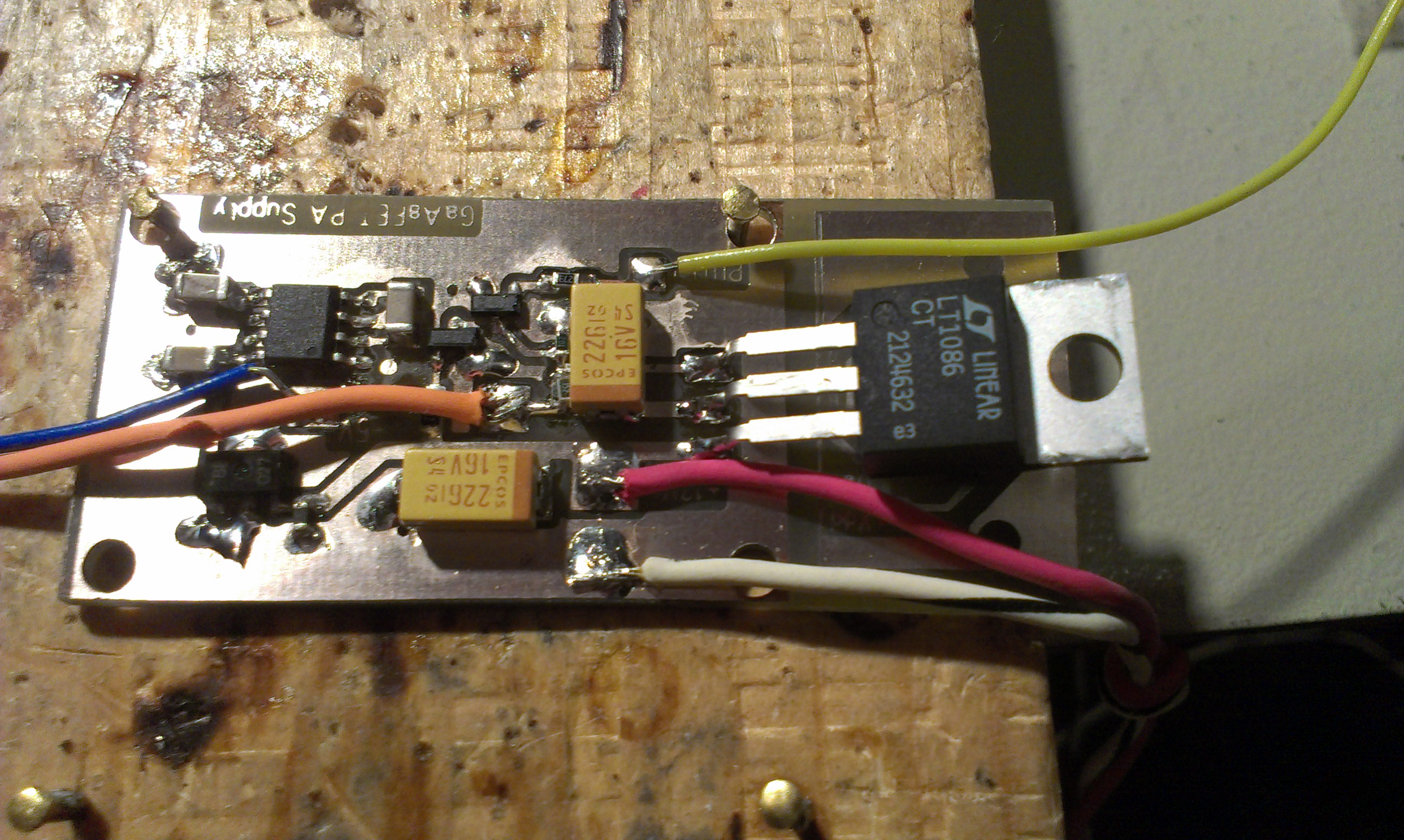 SSPA power supply board
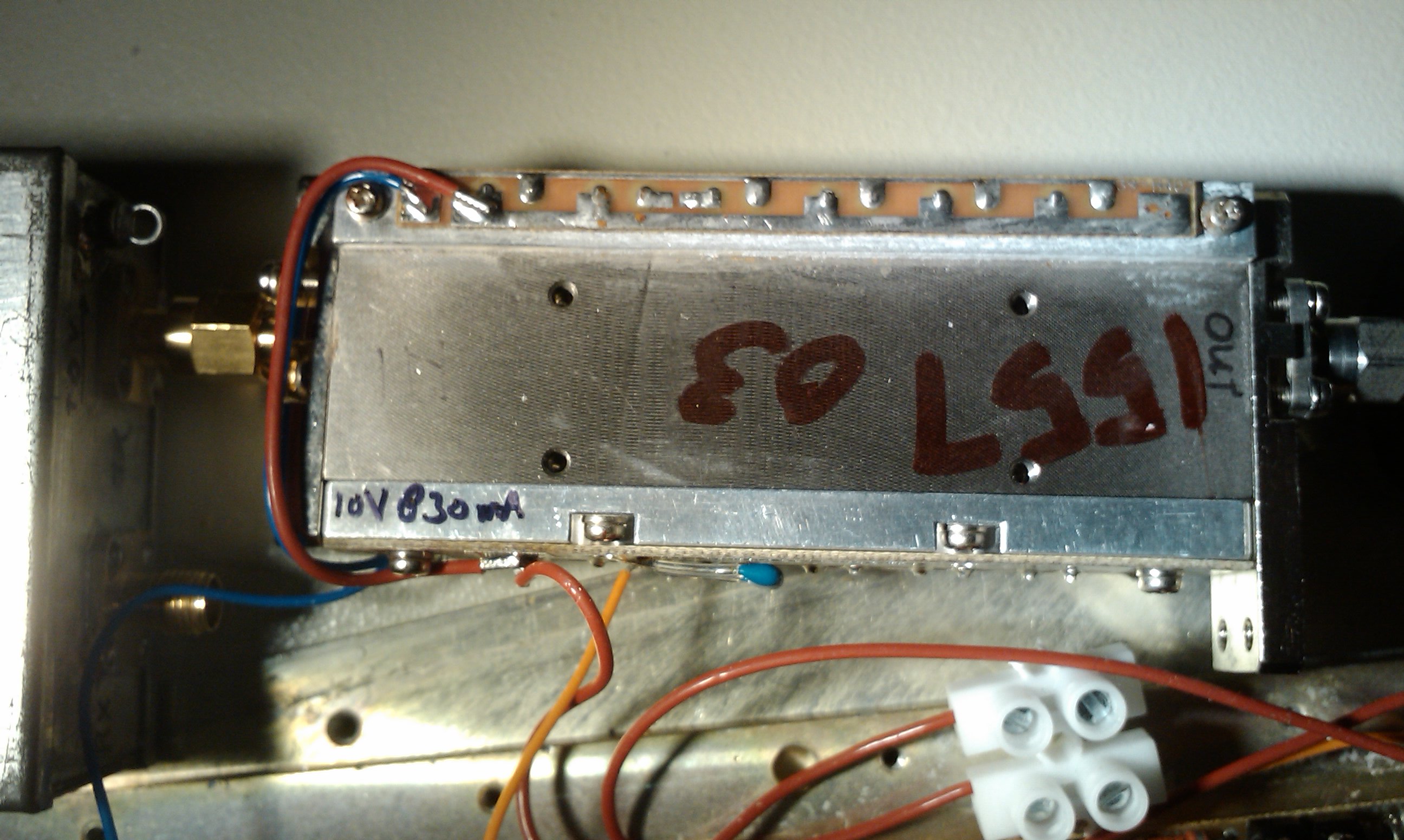 30dBm SSPA
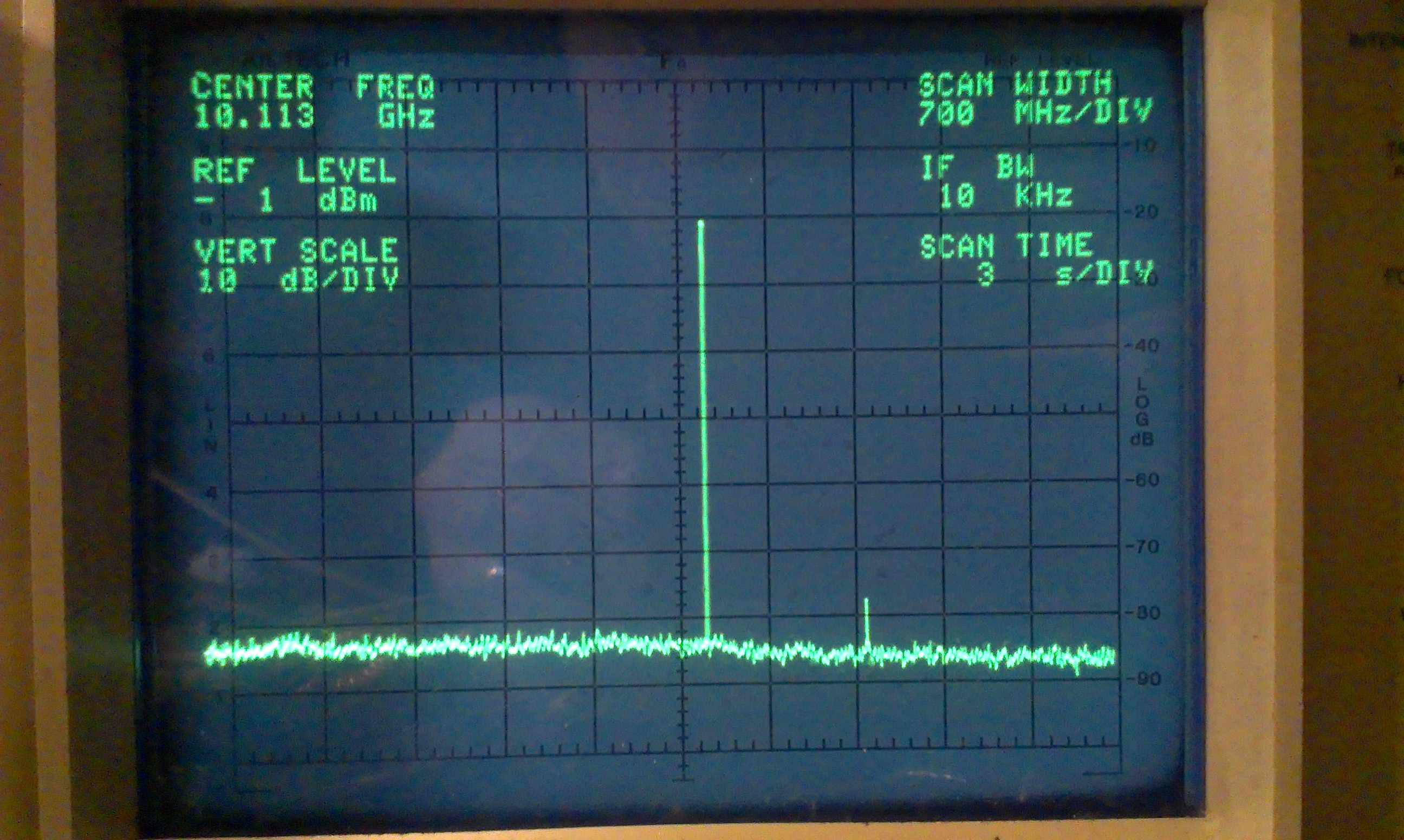 Output Spectrum at 30dBm SSPA
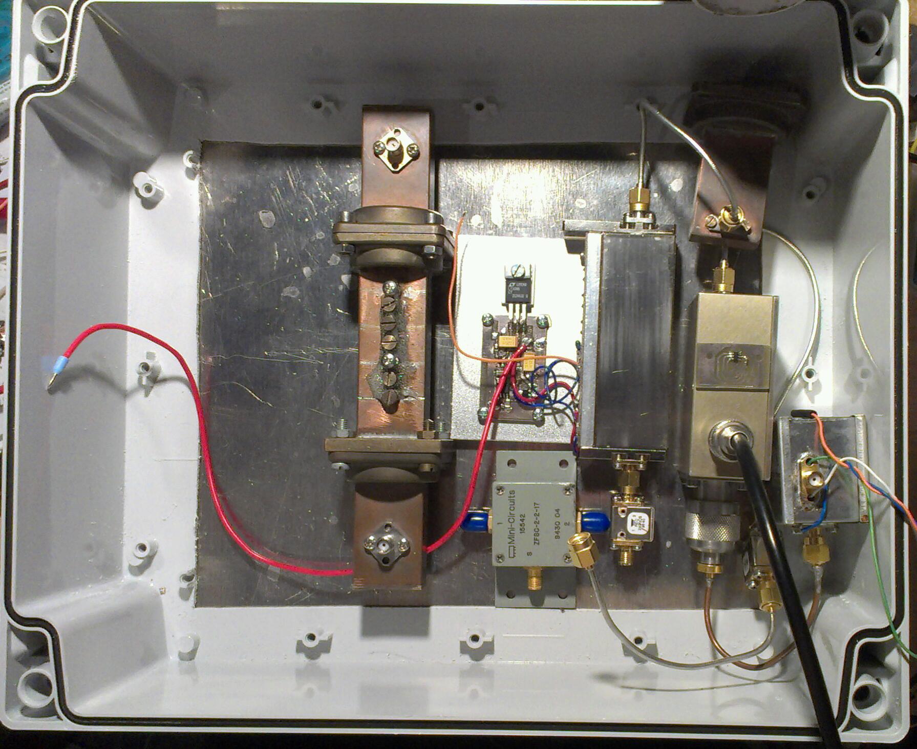
All modules for the 10GHz beacon inside the Fibox. 5mm Thick aluminum plate on the bottom for heat exchange.
From left to right: Waveguide Bandpass filter. SSPA power supply, ZFSC-2 power splitter (for 10MHz reference), SSPA with isolator, x8 Multiplier, Waveguide / SMA transition, PLL-VCO.
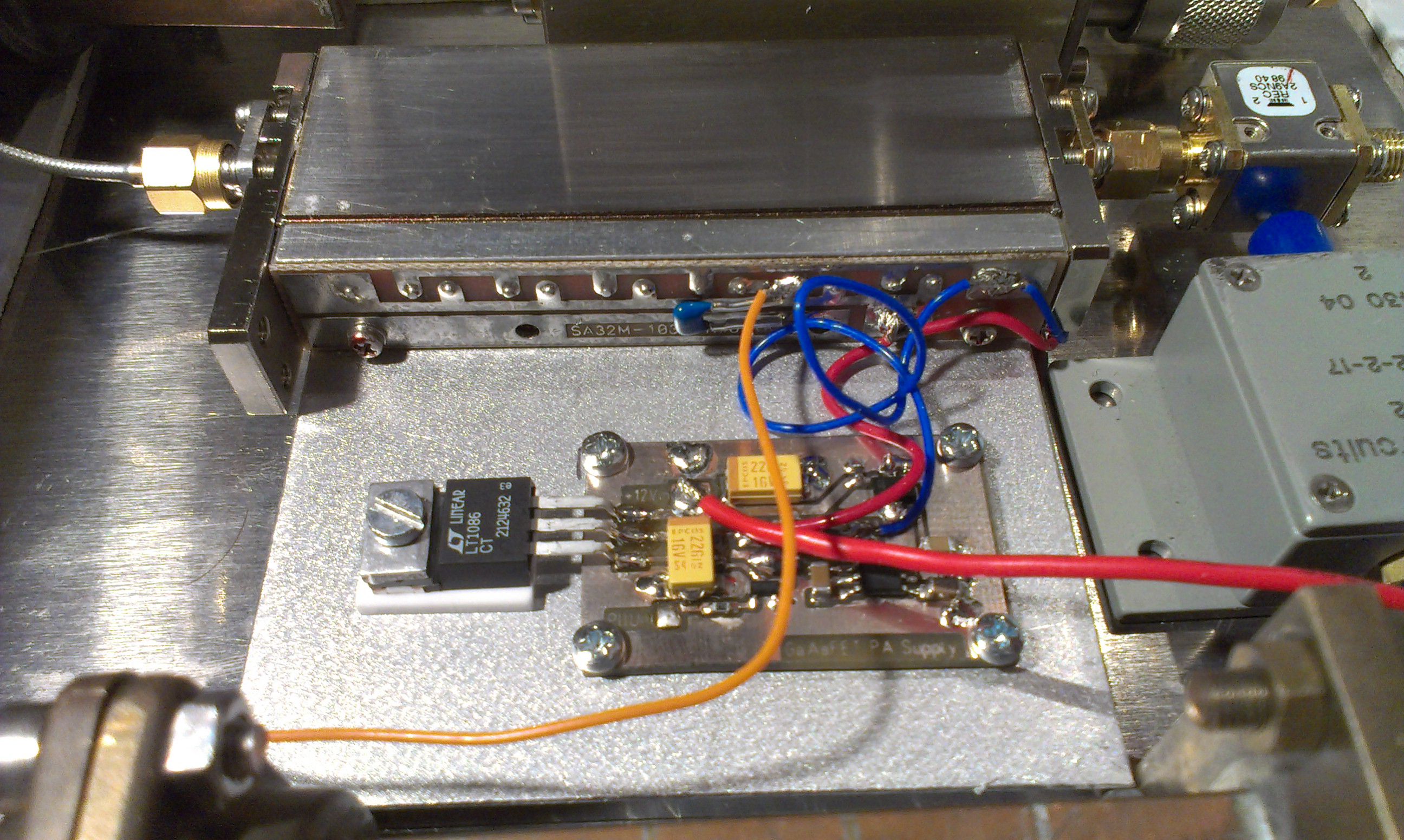 Closeup 10GHz SSPA + PSU
Will there be enough room left in the 289x239x107mm box for the modules of the 24GHz beacon ?
After receiving the modules for the 24GHz beacon from Bart pe1pfw, it was determined that this box is a bit too small to accomodate all modules for both beacons, so the next larger size Fibox (344x289x118mm) was obtained. Also a suitable 5mm thick Aluminum bottom plate for this box was ordered from the Alu-shop.
Update 2013-05-01: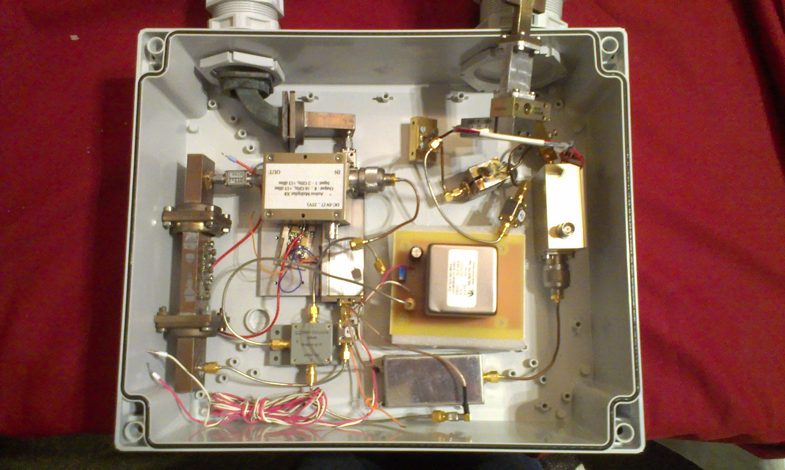
This picture shows (almost) all modules for the 10 and 24GHz beacons, fit together in the box..
Tomorrow 2 big holes (M50 and M63) for the antennna tubes will be milled and the bottom of the box be sawn out to accomodate for the aluminum bottom plate. This will be done on my collegue Ronald's DIY CNC machine.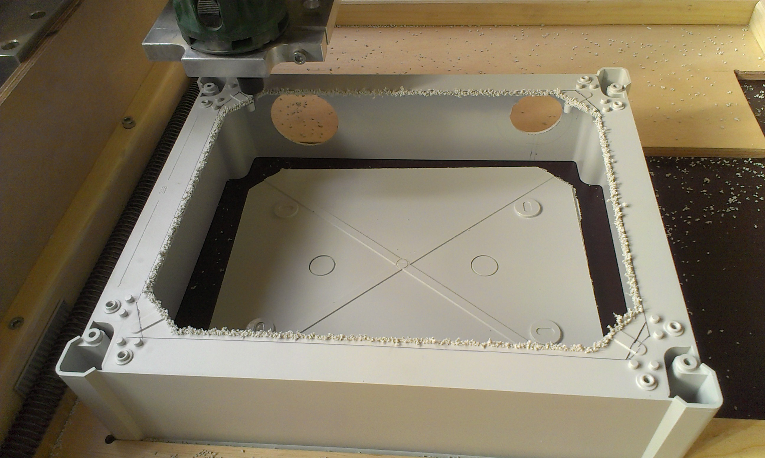 Bottom cut out.
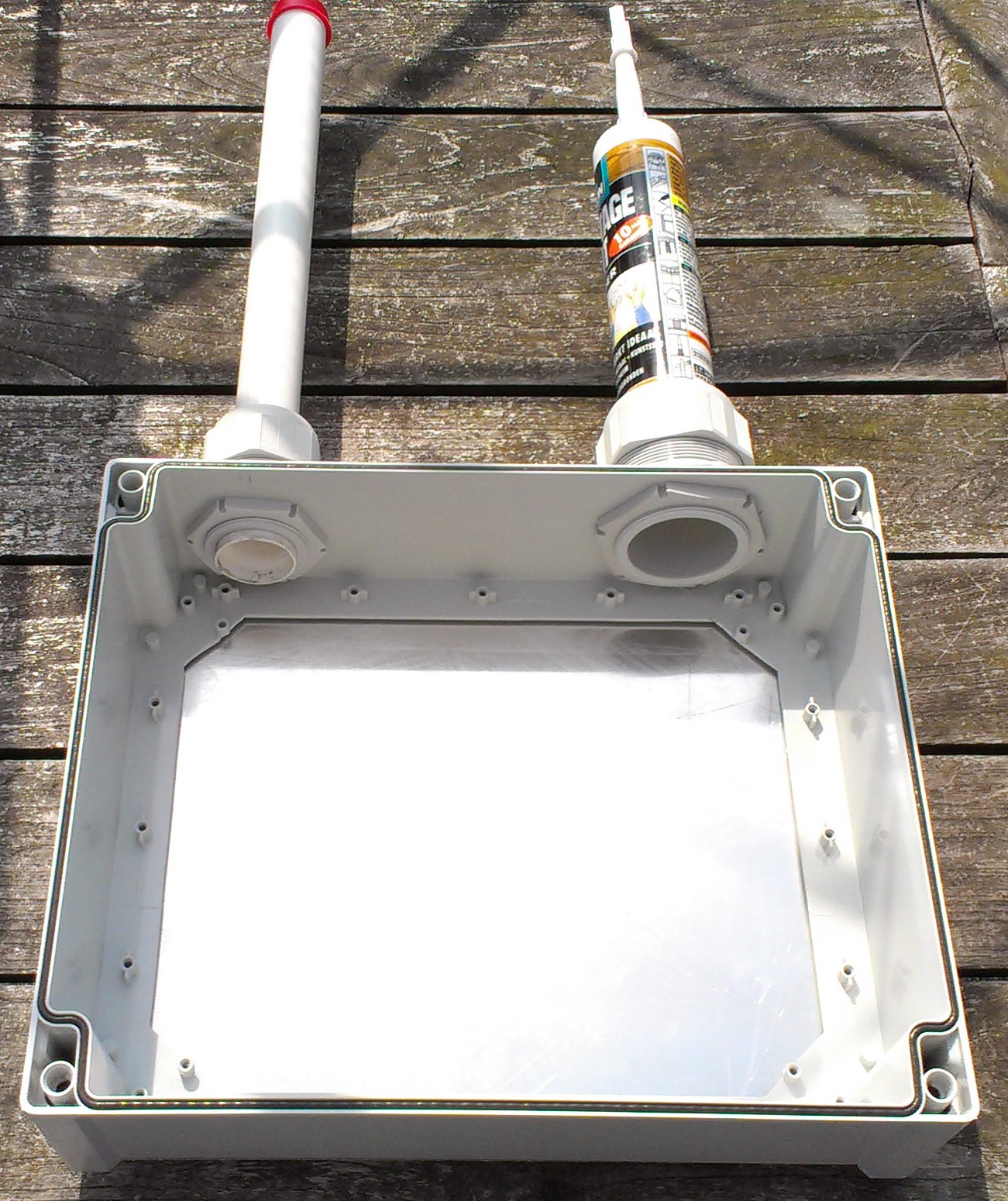 Alu bottom plate, M50 / M63 swivels and tubes for both slotted waveguide antennas mounted.
10/5/2013: The 24GHz beacon is now being tested on the bench (all modules interconnected). The signal, as received by a simple DB6NT 24GHz transverter on the other end of my shack, sounded a bit wobbly. This was improved significantly after adding a 10uF X7R capacitor from the DOCXO MV89a's Vtune pin to ground. This pin is being used with a 20turn variable resistor connected to Vref, to set the 10MHz reference exactly spot on.
1/8/2013: All modules built into the Fibox case, and seam between case and alu bottom was made waterproof using acid free silicone compound. All bolts and holes in the bottom plate were also treated with the compond. Then outdoor testing in my garden was started.
7/8/2013: After some more testing, a problem with some spurious / sidebands (at -40dBc) at 6,1kHz intervals above and below the main carriers became apparent. This spurious seems to be caused by the ICL7660 inverter running at that frequency. The inverter was expected to run at 10kHz, but a rather high load on the -5V output (the bias current draw by the 10GHz PA was measured at 160mA) could be causing the lower switching frequency. The 6,1kHz ripple leaks via the +12V power supply rail to other components, e.g. to the DOCXO which seems to need a very clean power supply. Adding some additional decoupling caps and exchanging the X7R caps for tantalum caps on the supply board helped somewhat, but not enough. Therefore a new supply will be built, with an LT 1054 CS8 instead of the ICL7660. As the LT1054 runs at 25kHz, filtering at this frequency will probably be easier.
8/8/2013: A new PA power supply board was assembled with a LT1054CS8 instead of ICL7660. Sure, I could have just desoldered the ICL7660 from the first PCB, but this way I still have a complete working spare board.
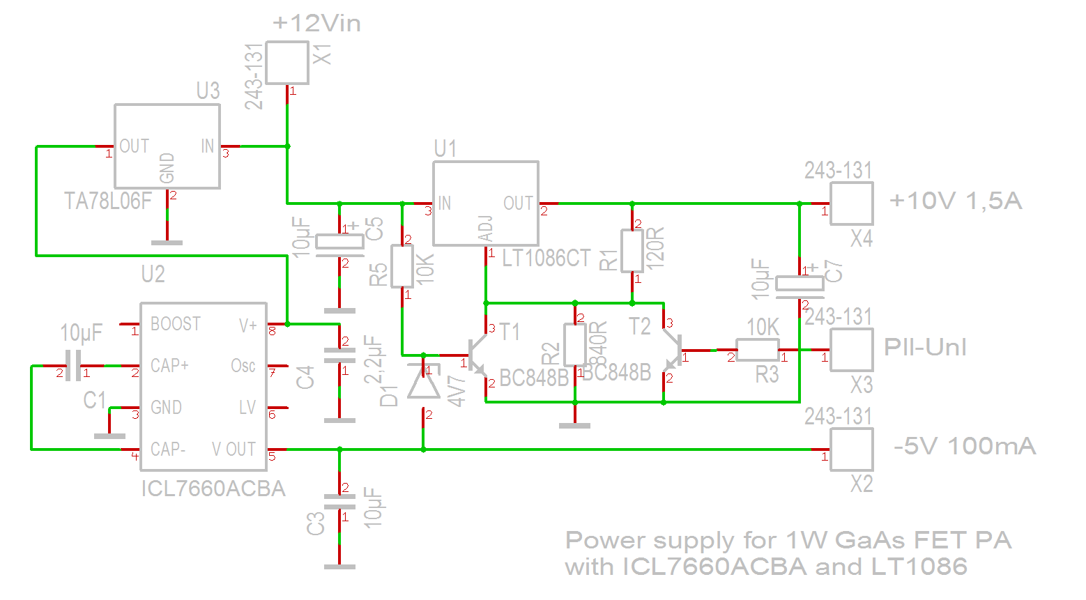 Power supply for 1W SSPA
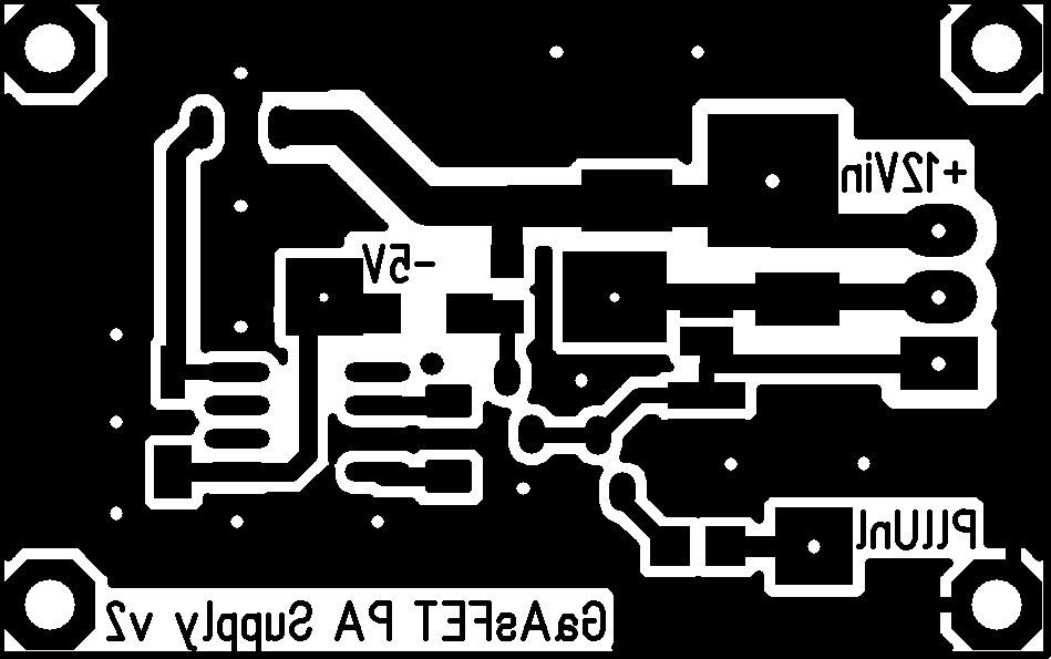 Power supply PCB v2
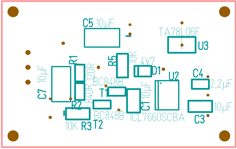 and component placement
Update 10/8/2013: The new 10GHz PA power supply board with a LT1054CS8 was installed.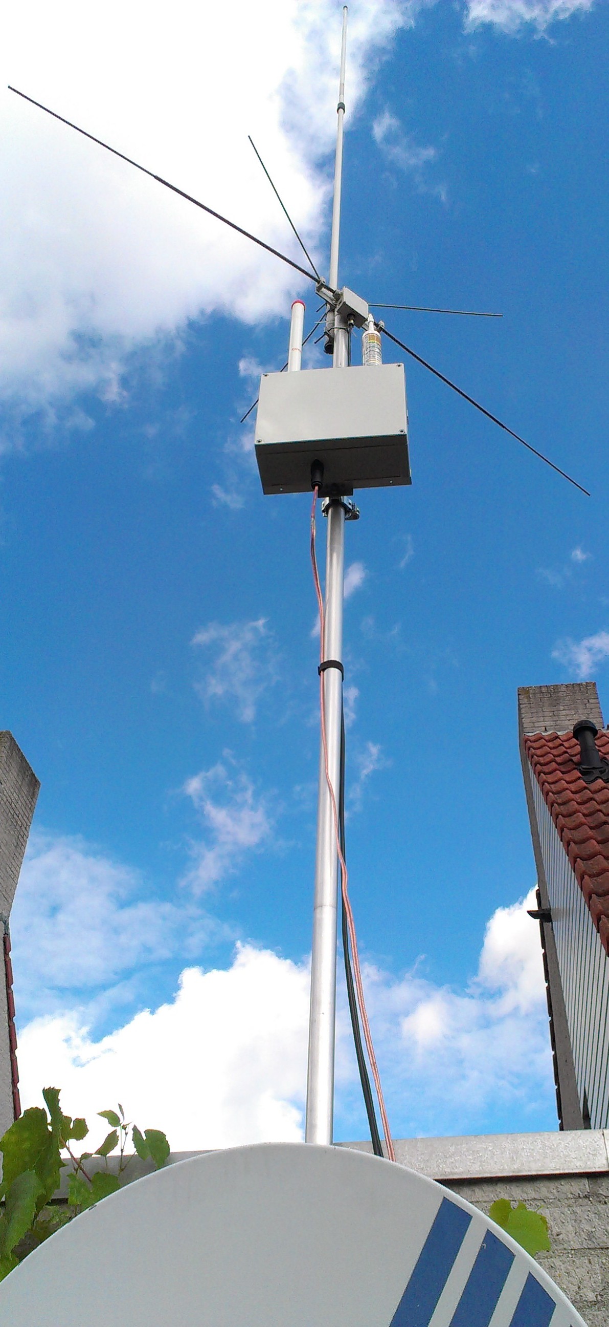 Some quick listening tests showed that the spurii at 6,1kHz intervals are no longer present. Unfortunately, at 24GHz there is still some spurious at + and - 25kHz, but the levels are much lower.
The 10+24GHz beacon is now installed and operational on an auxillary mast on my garage for testing purposes.
On top of this mast is my vertical whip (CX902) for 2m/70cm/23cm, and an open dipole for 4m.
The beacon box is just below these antennas.
The altitude of the beacon antennas is approx 5m asl. Once testing is completed and the beacons are performing reliably, the beacon will be moved to a more permanent and much higher location.
Output power of the 10GHz beacon, measured at the WR90 flange connecting to the antenna: +26.3dBm (427mW).
Output power of the 24GHz beacon is at least +23dBm.
When you hear one of the beacons (10368.815 and 24048.815) please send spots to DX cluster or beaconspot.uk ! Tnx.
Update September 2013: Attempts were made to run the beacon from a 24-28V power supply using two DC-DC converters: A TSR1-24150 (15V out) followed by a LT1086 as low-noise 12V supply for the 10MHz DOCXO and a separate TSR-1-24120 (12V out) for the rest of the beacon. Unfortunately this was not very succesful because the current draw was too high resulting in an overheated TSR1-24120 DC/DC converter. An extra TSR-1-24120 was added to split the load but even then the TSR's became very hot (+70C in open air). So a different solution was needed.
Update October 2013: After discussing this issue with Bart PE1PFW, he came up with a solution: He supplied a high-efficiency DC-DC converter pcb, based on a LM22670MR-ADJ, generously capable of providing enough power (12V/3A). It has a enable-input, so it can be controlled by the CW-ID generator PIC (with poweron_delay). The picture below shows the new DC/DC converter pcb mounted just beside the 10V/-5V regulator board for the 10GHz sspa: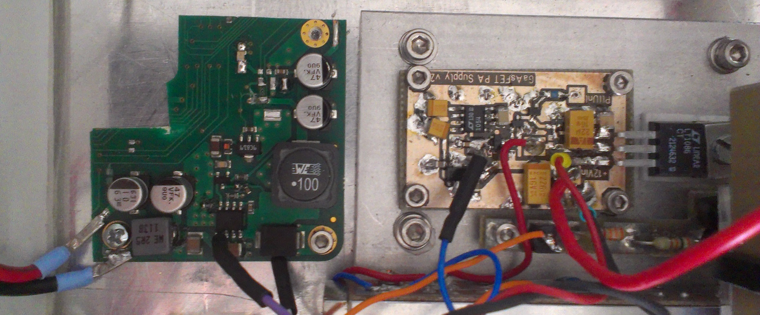
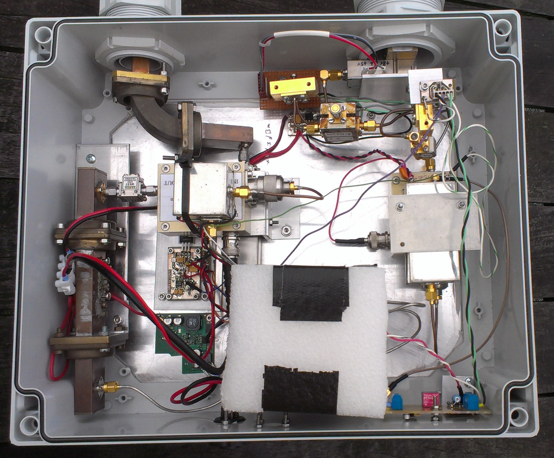 Inside the beacon box.
 - Update 14/10/2013: The beacons are now back on air at test location (in antenna mast on my garage) at 5m asl.
- Update 30/11/2013: Today the beacons were relocated for testing to tower (+9m ASL) on Radioclub de Bevelanden PI4Z (qth loc: JO11WM58ce ). Please spot on cluster or Beaconspot.uk when you hear one of the beacons.
Update 20/4/2014: After some maintenance work and improvements the beacon is back on-air at the Radioclub tower. The work involved:
- Improvements to 10GHz beacon: I replaced the half-blown SSPA with a new one. 10GHz power output now +31,2dBm (1,2W). Also, the antenna matching was improved (with tuning screws in the waveguide) so that most of the power is no longer absorbed in the final isolator....
- This resulted in approx. 10dB more radiated power.
- Improvements to the 24GHz beacon: Replaced sma connectors, a faulty isolator and improved insertion loss of the 12GHz BPF. Now the final x2-multiplier / PA stage gets enough drive (+4dBm) to deliver maximum output power (+23dBm or more). Before, the output was measured to be about +0dBm.
- Repaired the 12V low-noise power supply circuit of the OCXO (a broken smd resistor at the LT1084 regulator circuit caused interruptions in the DC voltage fed to the OCXO).
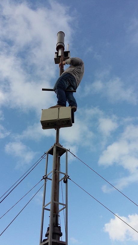
Update 5/5/2014: After the IARU contest of may-2014, the beacon box was relocated to the top of the tower (+13m ASL) on the club building of Radioclub de Bevelanden PI4Z.
The picture below shows the beacon and the absence of obstacles in the near surroundings: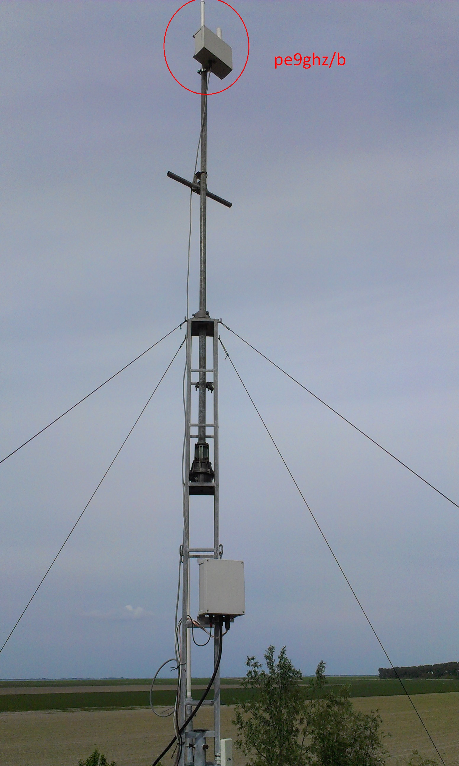
may 2014: We have started preparations to add a 5,7GHz beacon.
Bart has supplied a complete module with PLL-VCO and SSPA delivering 1W output power at 5760,815MHz. There's just enough space in the beacon housing to accomodate this module.
Now in the next coming months a slotted waveguide antenna will be constructed.
update 2nd october 2016: After the IARU contest of October 2016, we've put in operation a new 6cm and 23cm beacon which is co-located at the tower with the 10+24GHz beacon.
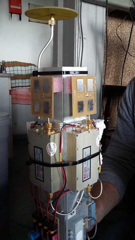 The new beacon was built by Bart, PE1PFW/DL1ARE. Frequency of operation is: 5760.8150 MHz and 1296.815MHz with -800Hz shift during CW-ID keying.
The antenna for the 5,76Ghz beacon consists of an array of 4 times Quad-Patch arrays(by WA5VJB) mounted at 90degrees in a circle thus implementing a sort of circular radiation pattern.
The antenna for the 1,3GHz beacon is a Wheel on pcb (also by WA5VJB). The antennas were kindly provided by Sam G4DDK.
more info and pictures will be added soon.
A note about Remote Control
To obey the (new) rules of Agentschap Telecom, with respect to unattended operation of Amateur Radio Transmitters without a special licence (BT) for "Onbemand Frequentiegebruik", I have installed a Koukaam NETIO-230B IP/web remote controllable PDU (Power Distribution Unit), so I can control the beacon's power-supply via a Web browser or Smartphone App from anywhere where I have (mobile) internet access.
Finally some measurement data (tnx Bart!):
- 10GHz waveguide bandpass filter
- 12GHz cavity bandpass filter
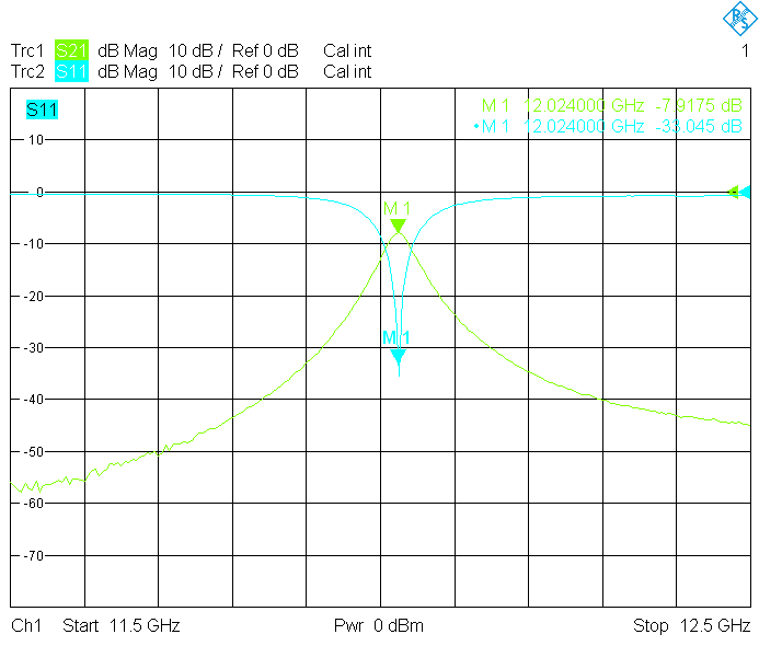
12GHz multiplier output, after cavity bandpass filters: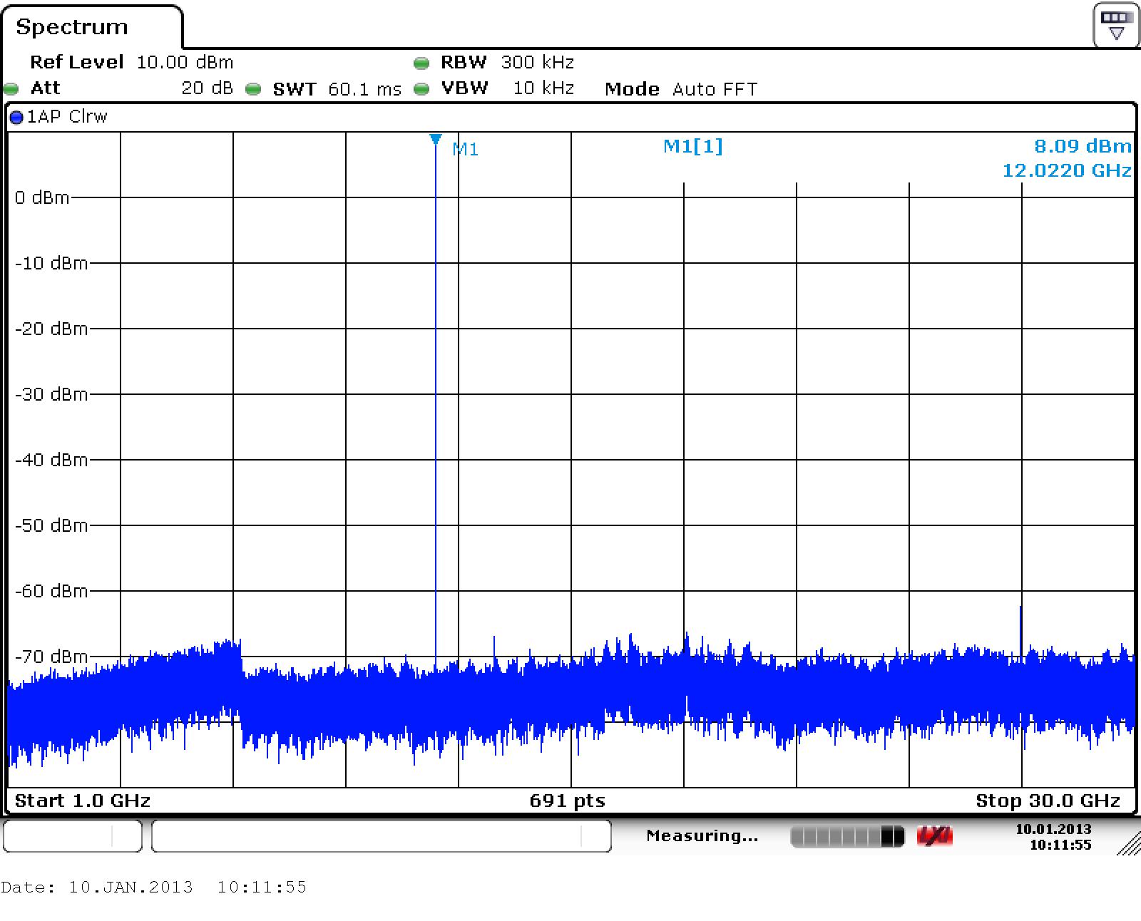
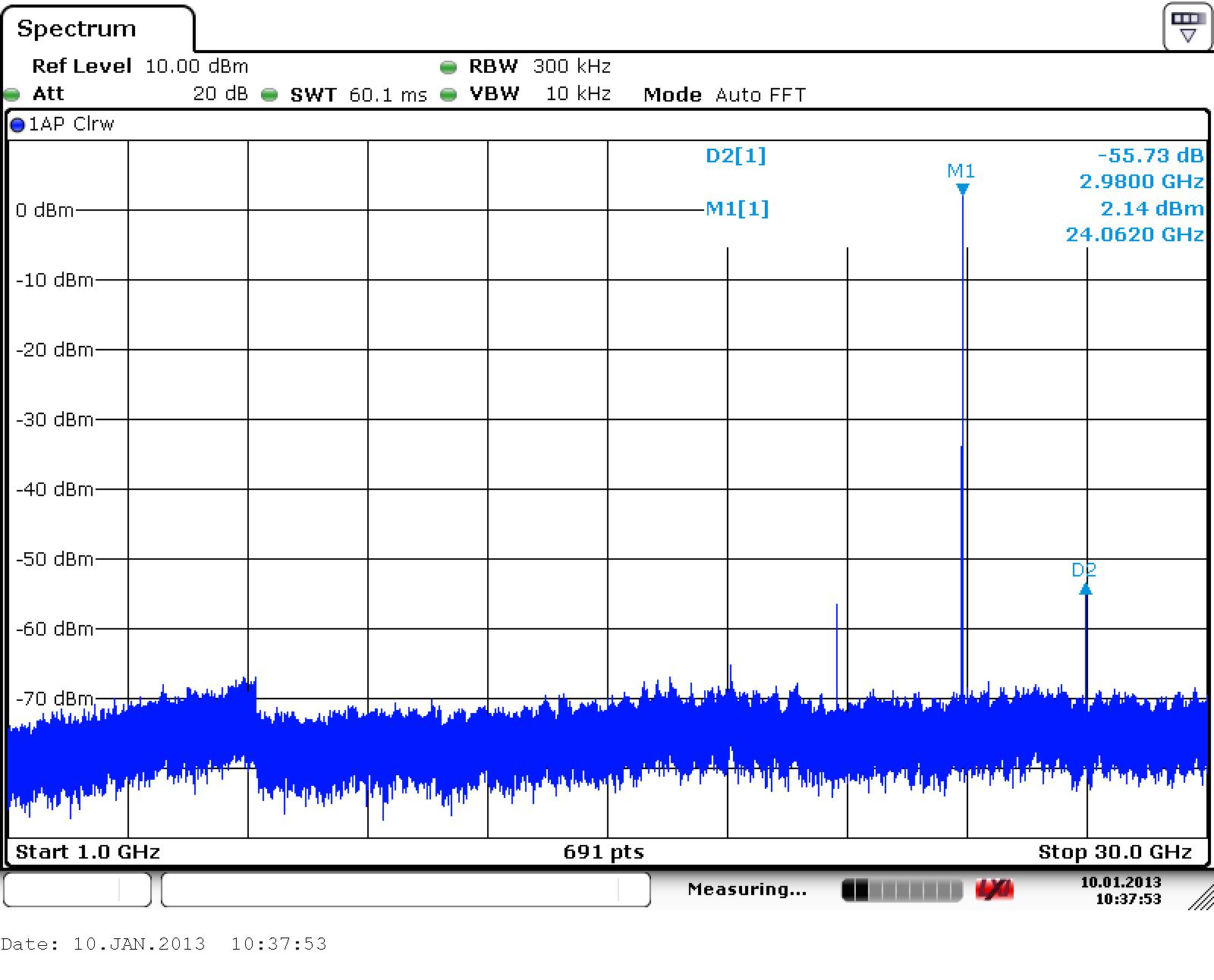
- 24GHz output, 23dBm at WR42 flange, spurious -58dBc:
- Total power consumption: 1,37A @ 25V DC input = 34W
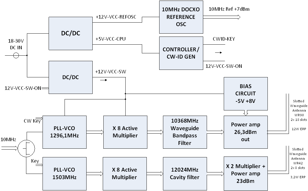
- Here's the schematic diagram of the beacon(s):
DXcluster Spots:
https://www.beaconspot.uk/beaconc.php?beaconcall=PE9GHZ&bandmhz=10368
https://www.beaconspot.uk/beaconc.php?beaconcall=PE9GHZ&bandmhz=24048
https://www.beaconspot.uk/beaconc.php?beaconcall=PE9GHZ&bandmhz=5760
https://www.beaconspot.uk/beaconc.php?beaconcall=PE9GHZ&bandmhz=1296
Update 2023-10: Due to water ingest the 1296.815MHz and 5760.815MHz beacons are currently OFF-AIR.
We are awaiting better weather conditions to climb the tower and remove the outdoor unit for inspection and repairs.
The 10GHz and 24GHz beacons are still operational.
Update 2024-05-05: 10 and 24GHz beacon has been taken off air and offsite to do some maintenance.
We have determined that for some reason the output power of the 24GHz beacon was reduced from 200mW to 50mW. Bart DL1ARE has taken the beacon home for modifications. We have a spare Milliwave OS5PO amplifier which will be added to increase the output power back to at least the previous power level of 250mW (maybe even 1Watt). The construction has to modified to add this amplifier.
Also there has been some water ingest thru the seam of the 10GHz antenna which has caused corrosion of the 10GHz waveguide bandpass filter and some other parts. This needs to be cleaned and treated.
Permission is granted to reproduce PCBs for personal / amateur radio / non-profit use only.
Any commercial use without prior permission from owner prohibited.
Page modified by Eddy on 2024-05-05
Previous page: Beacon-PLL
Next page: 70MHz