Wavelab24GHz transverter
Intro
In 2022, I acquired a "Wavelab 24GHz module" and Maarten PA0MHE's add-on pcb for the module, with a lot of parts already pre-assembled by the PCB factory.
The remaining components were sourced from a well-known electronics parts store M.....com.
Pics
Here follow some pictures of the project "Wavelab 24GHz transverter". I always find the mechanical construction the most challenging.
Tip: When you right-click on an image, then select "View image in new tab/window" or something similar, you can open the full resolution pictures for the best viewing detail.
Here, trying to program the ATtiny MCU using an ArduinoISP. It failed at first, because the on-board ADF4351 PLL IC's were not yet powered thus putting too much load on the ICSP/SPI lines from the programmer.
After completing the powersupply section (U33 +5V-RX and U52 +3V3 LDOs), and powering the board, the programming of the ATtiny was successful.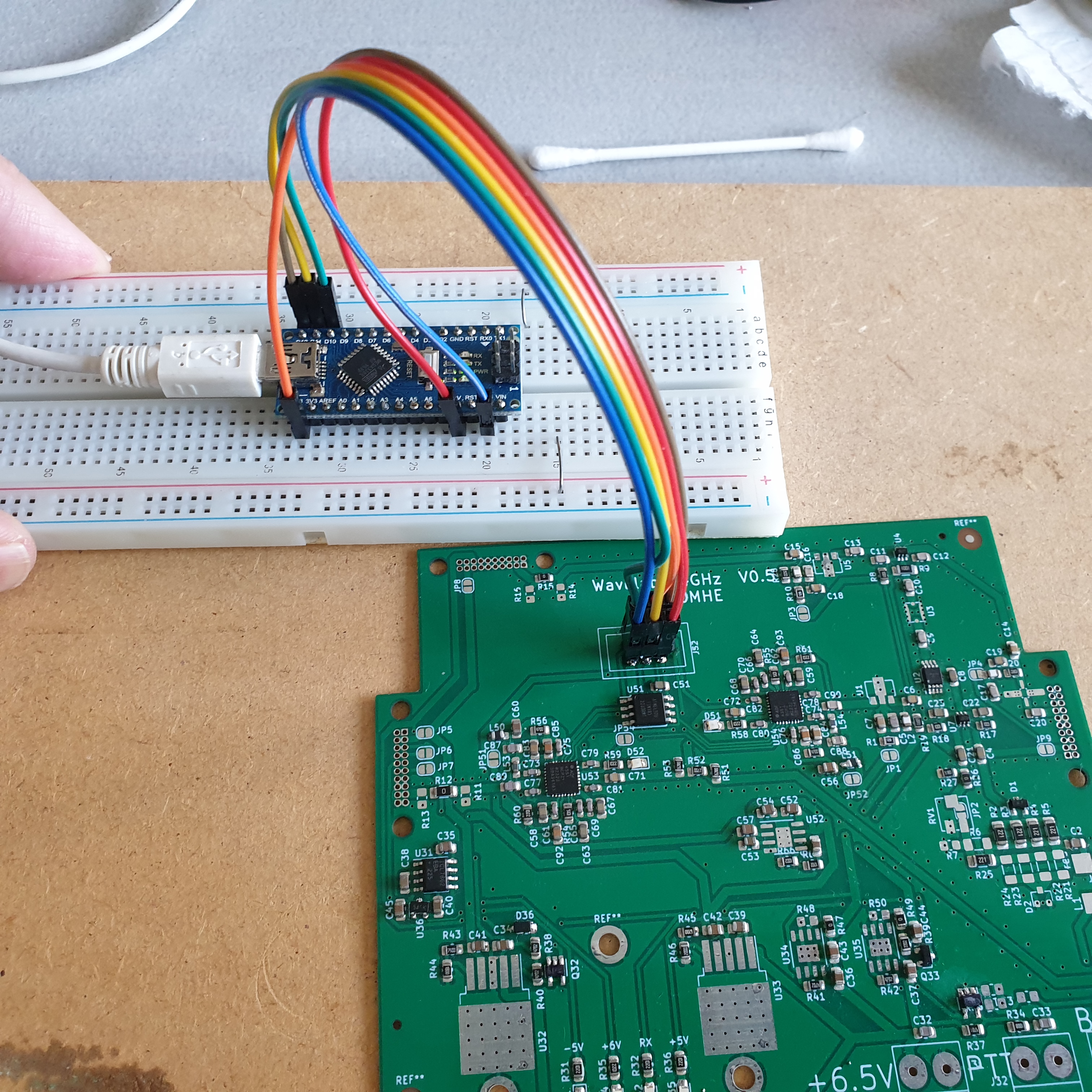
After completing assembly of the Power supply section (LDO's), during testing the functioning of the PLL chips, I found that one of the ADF4351's didn't work (produced no signal and lock-led didn't light).
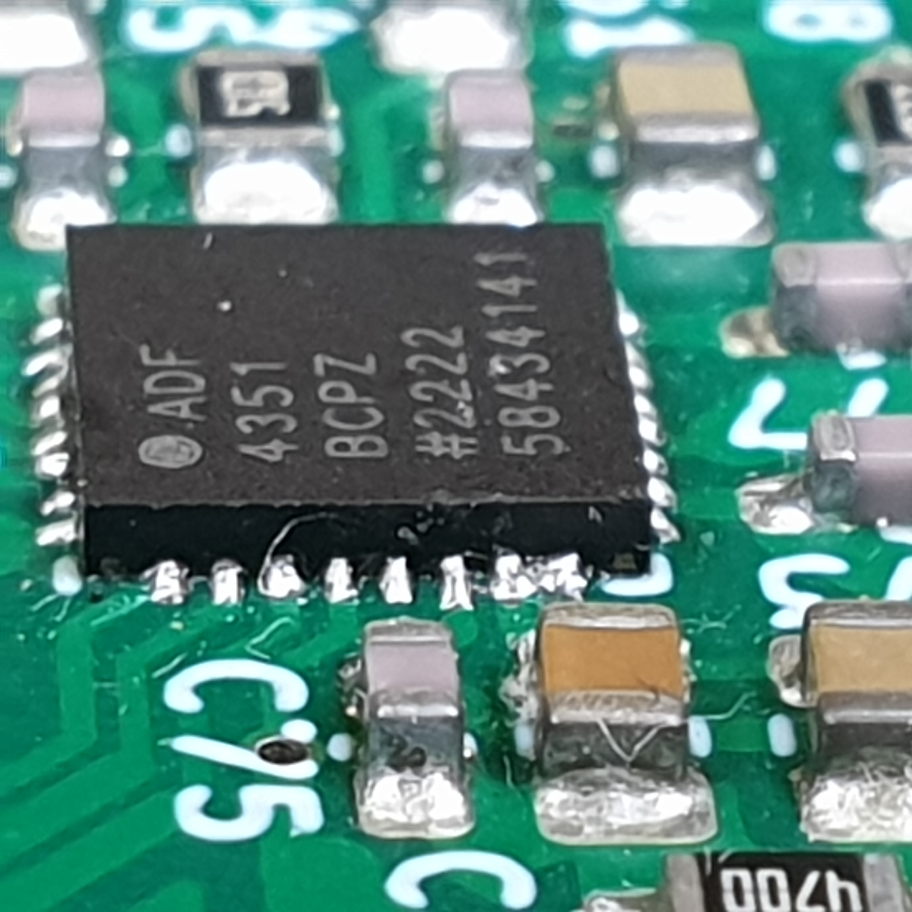
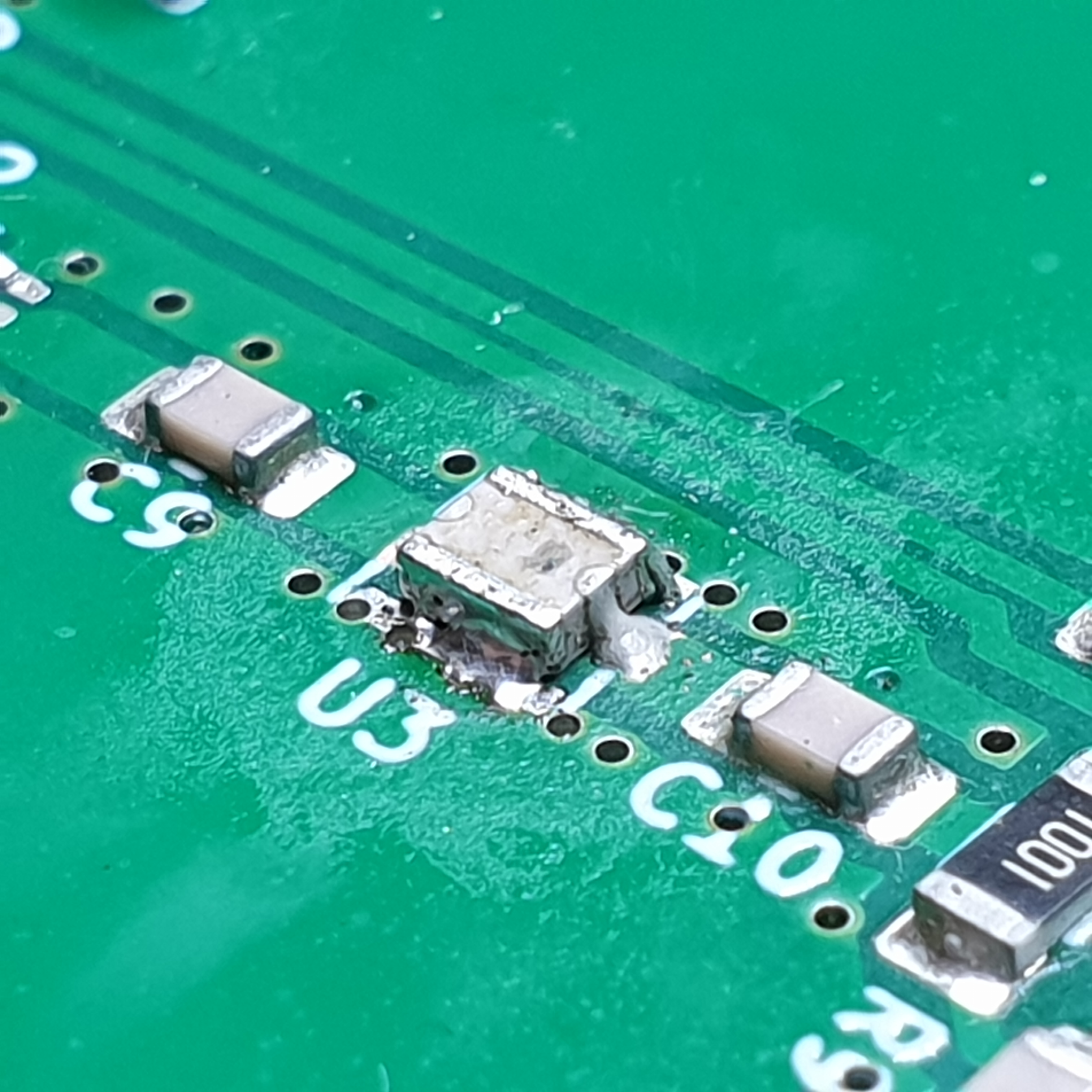
Using a DMM, I measured a short to ground (should be floating) on two of the decoupling C's around the PLL Chip: C75 and C85. A close-up picture shows the culprit: A solder-blob short between two pins of the ADF4351. This came straight from the Chinese PCB-factory!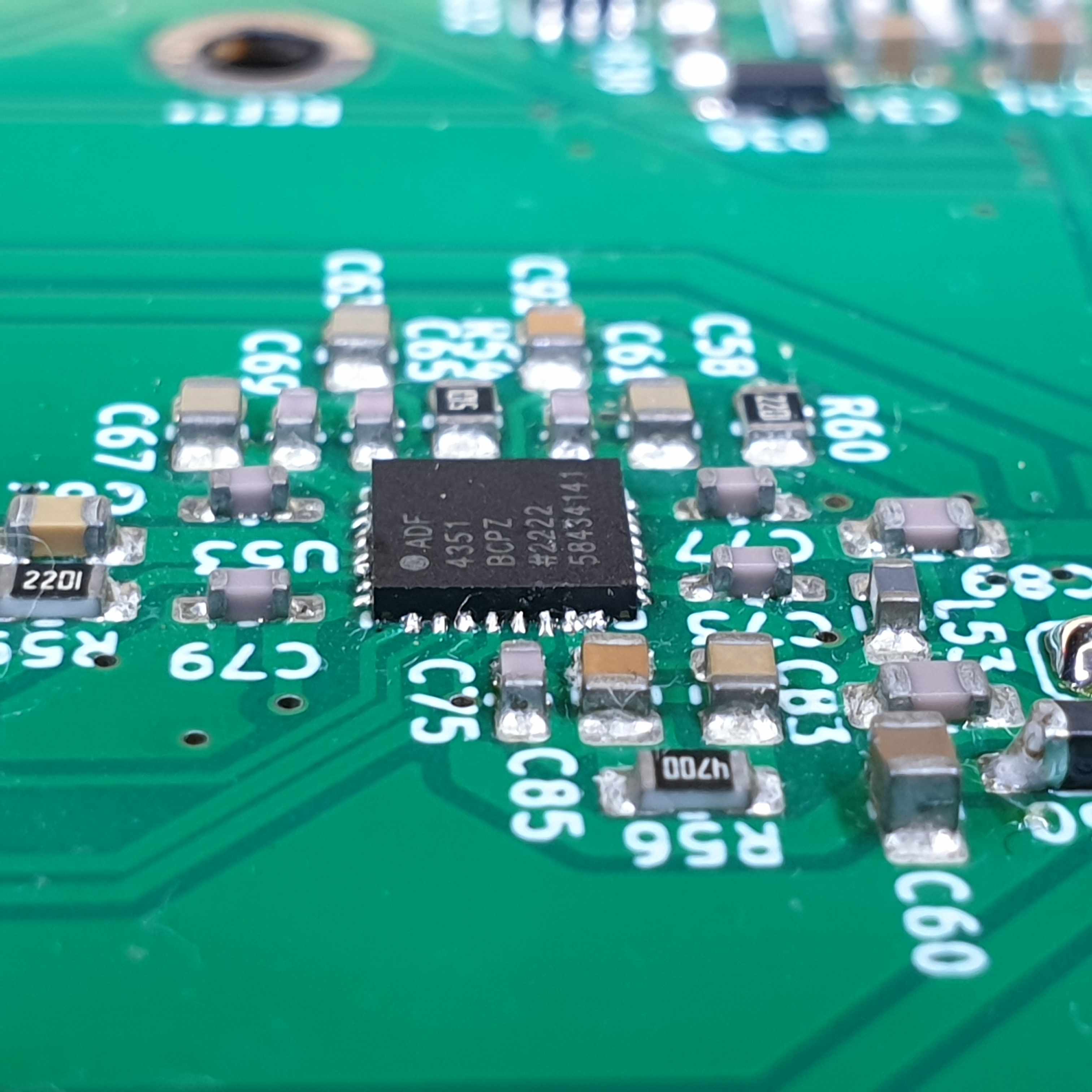
Detail of the short-circuit on the PLL chip:
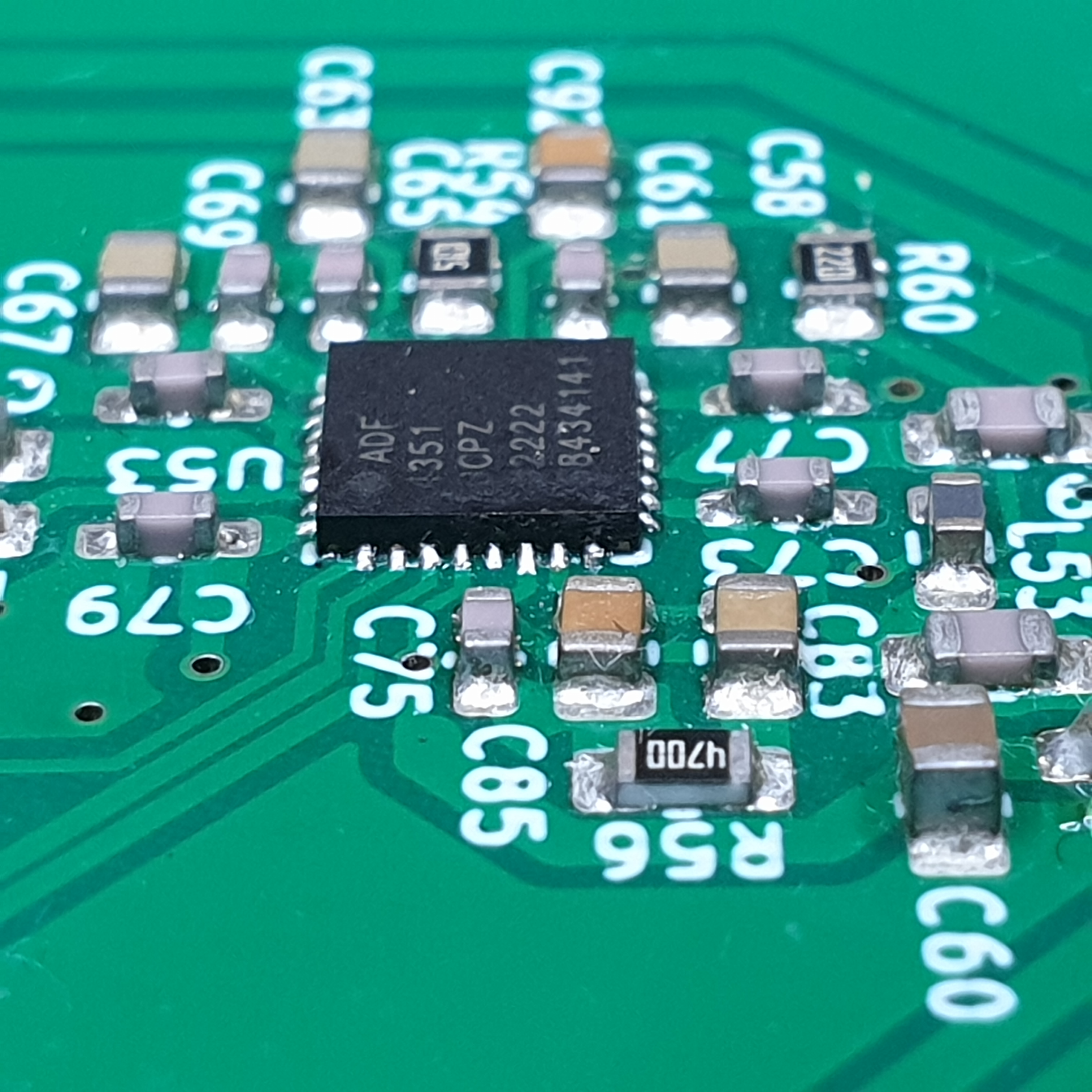
It was solved using a bit of solder-flux and solder-iron with small tip. Here's the result after re-flowing:
One of the hardest parts to solder I think was the filter U3:
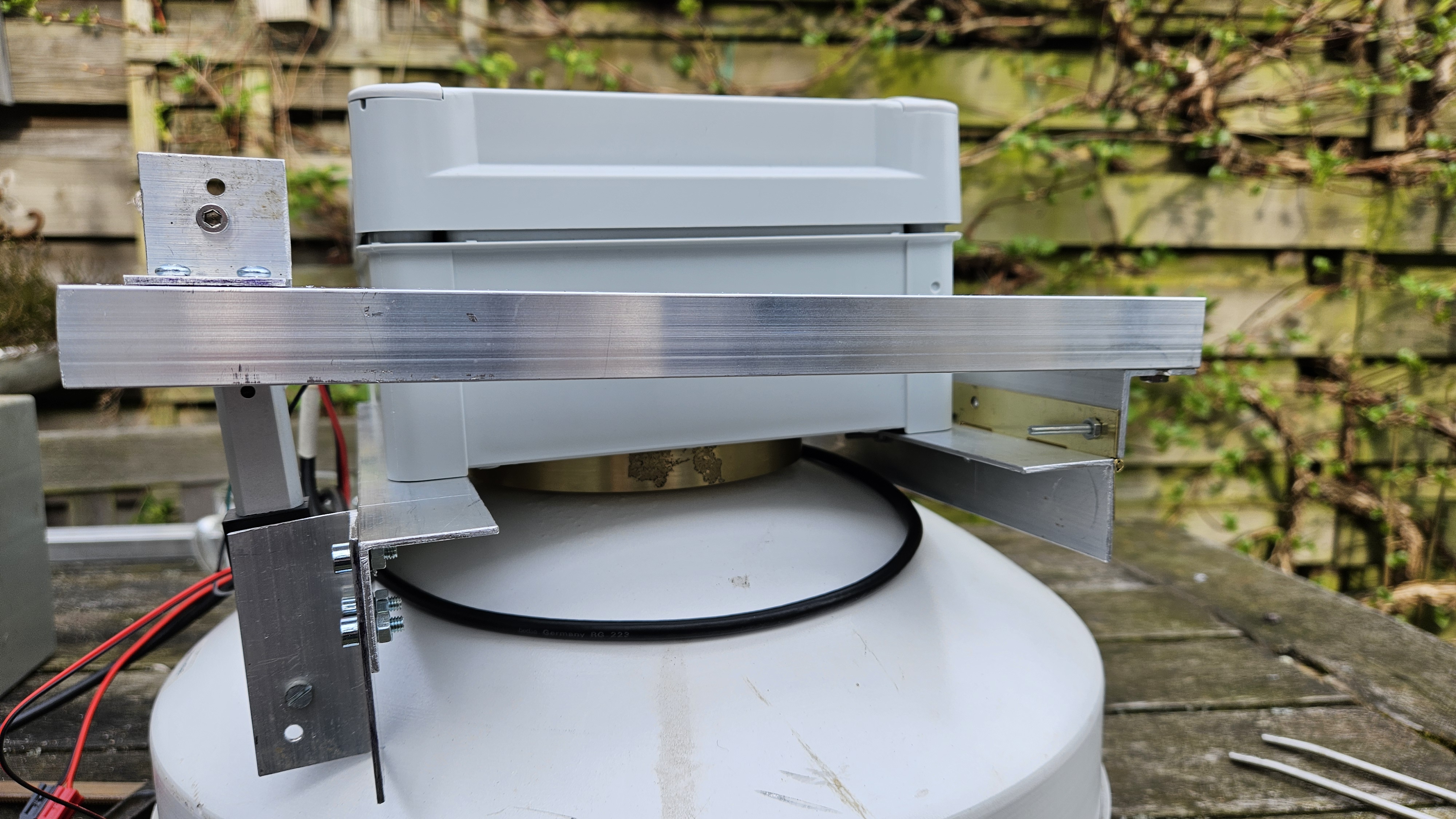
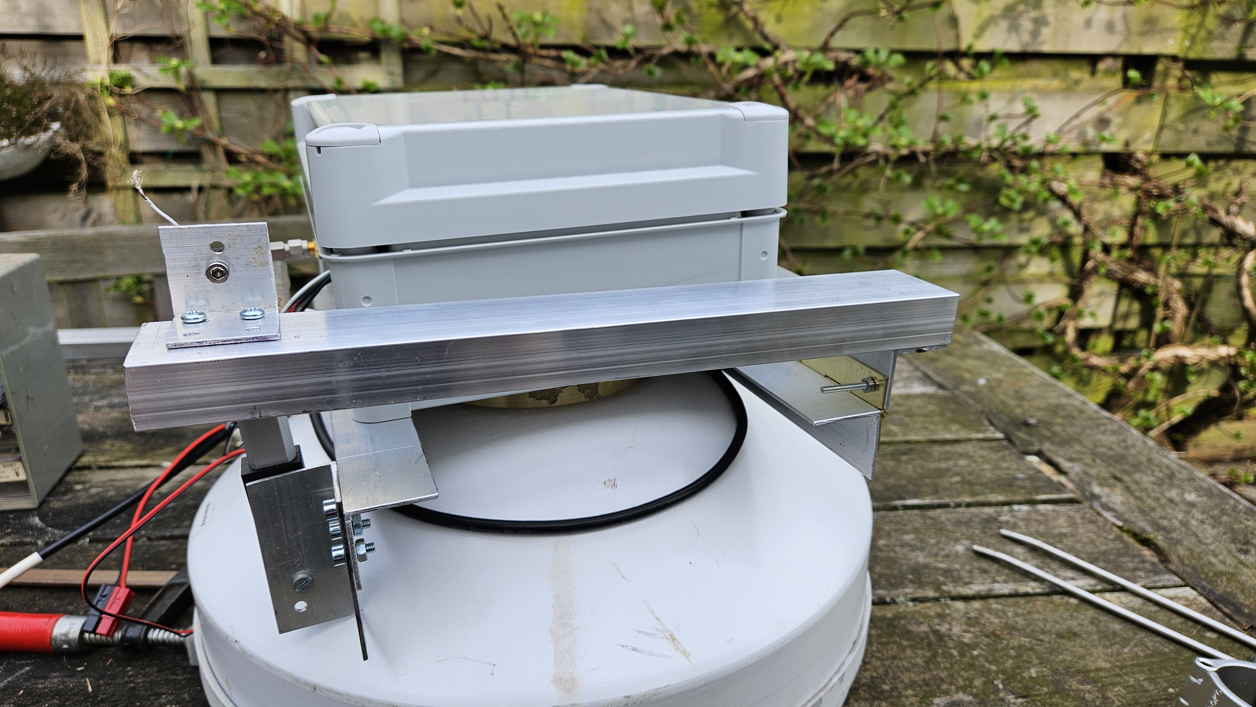
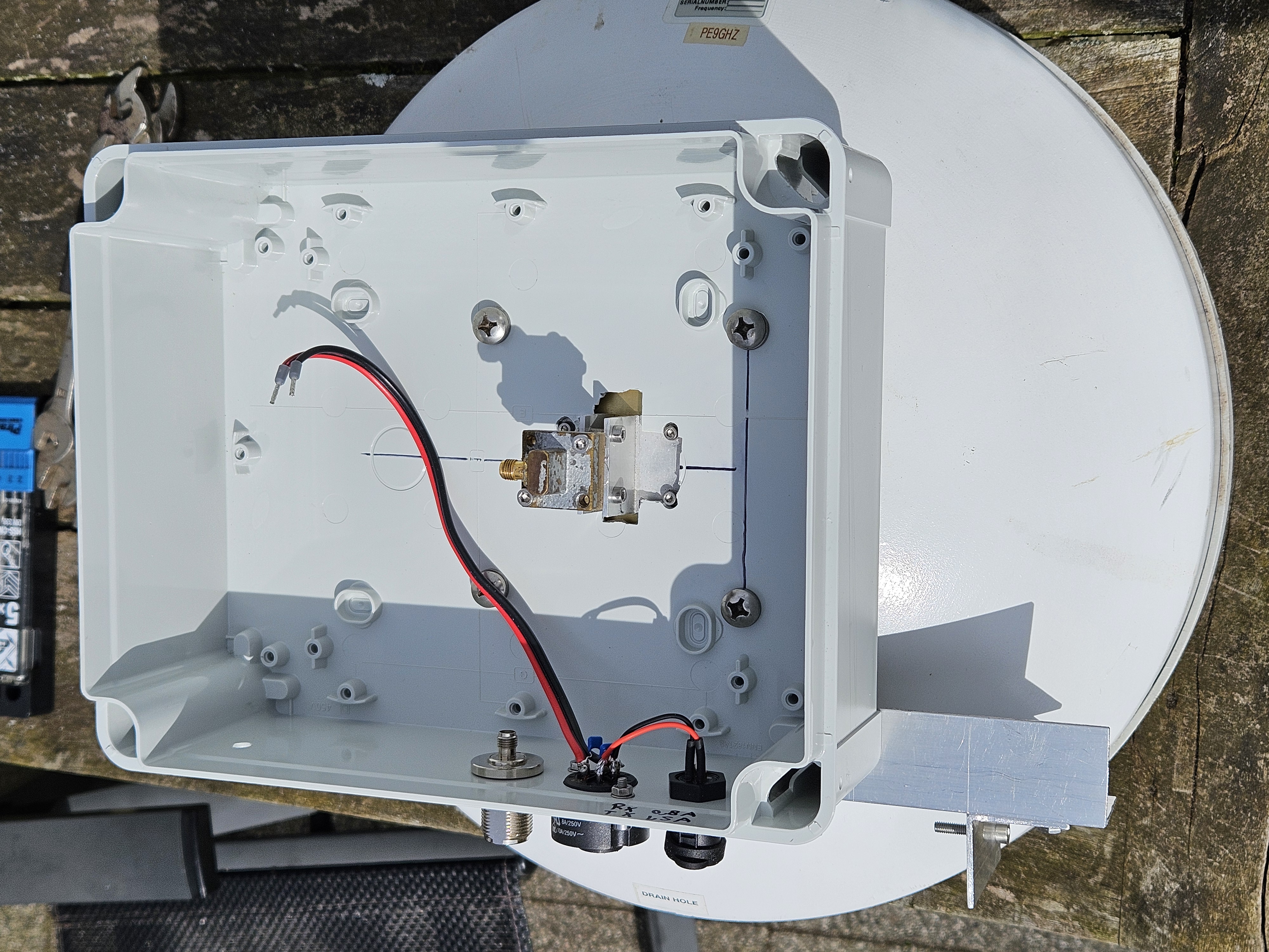
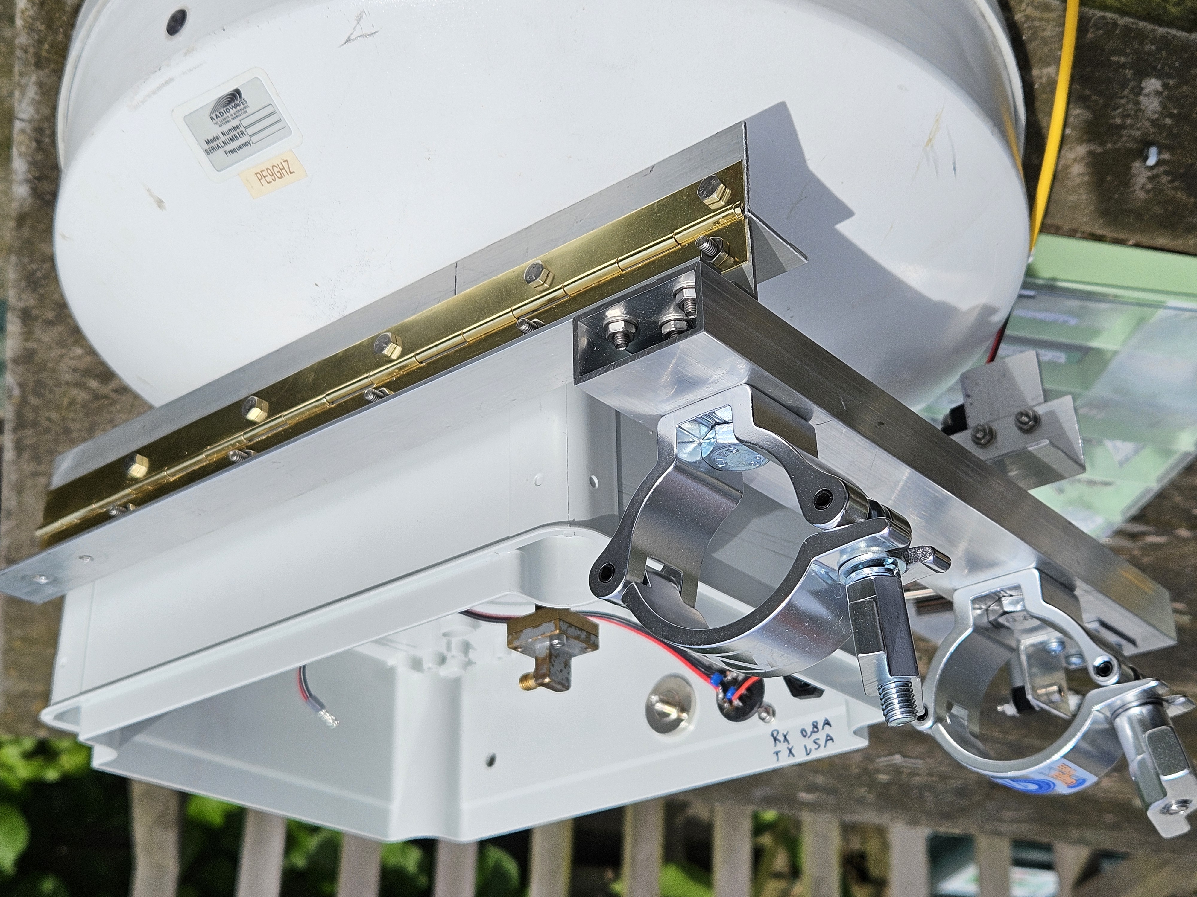
Below follow some pictures of the mechanical construction of the transverter unit, mounted directly behind the 34cm prime focus dish, in an IP67 ABS box (Schneider-Electric Thalassa series).
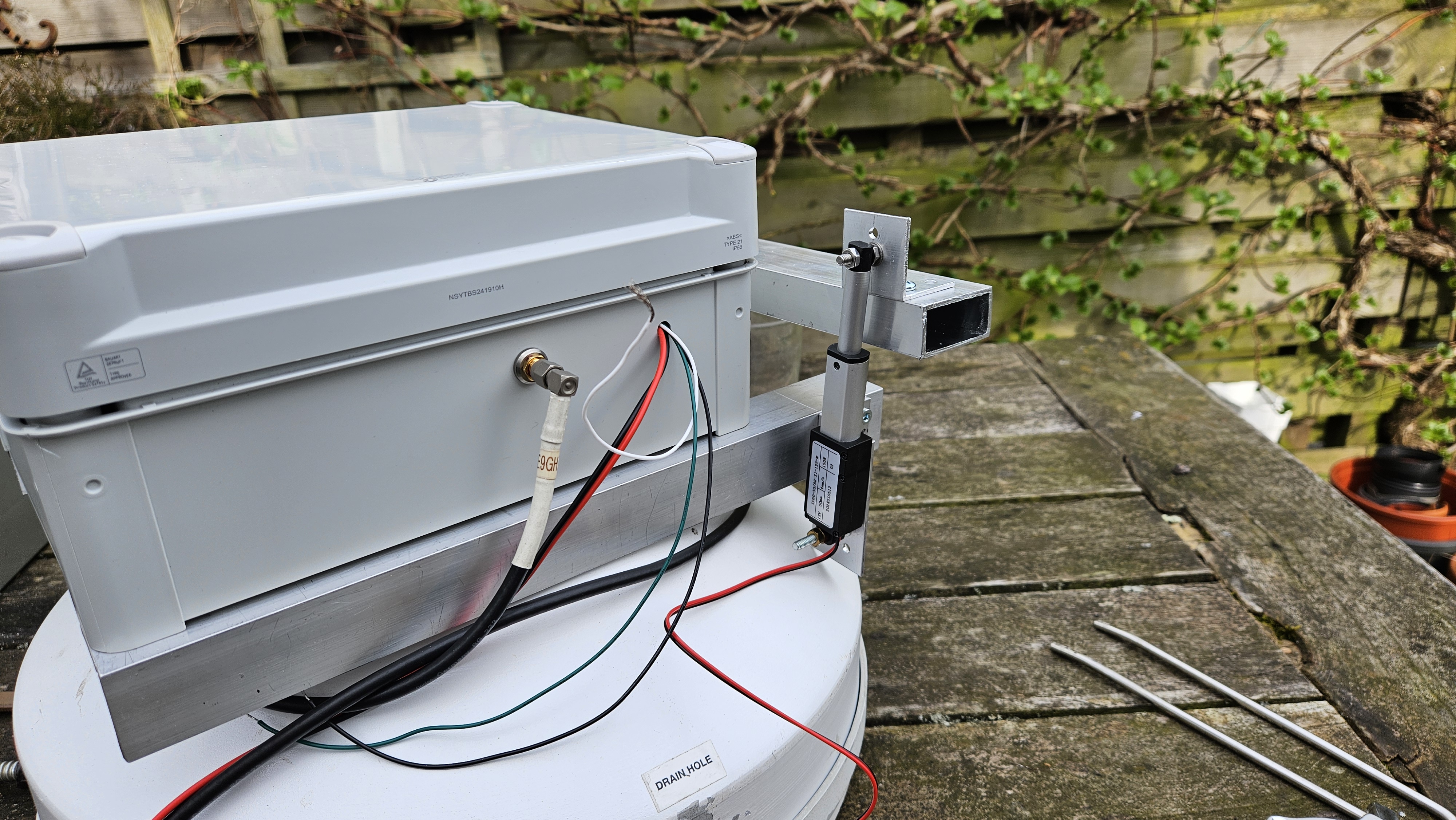
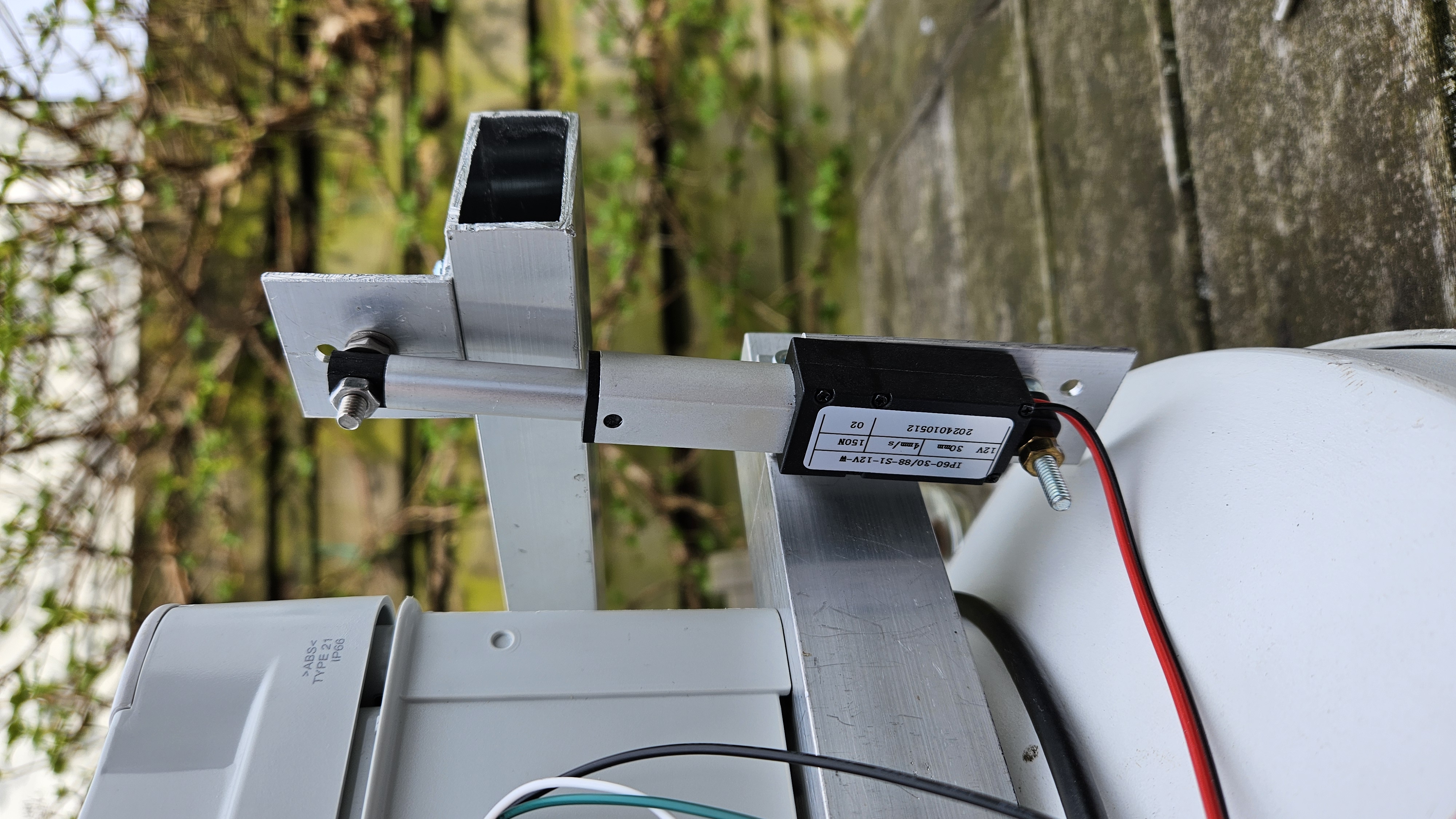
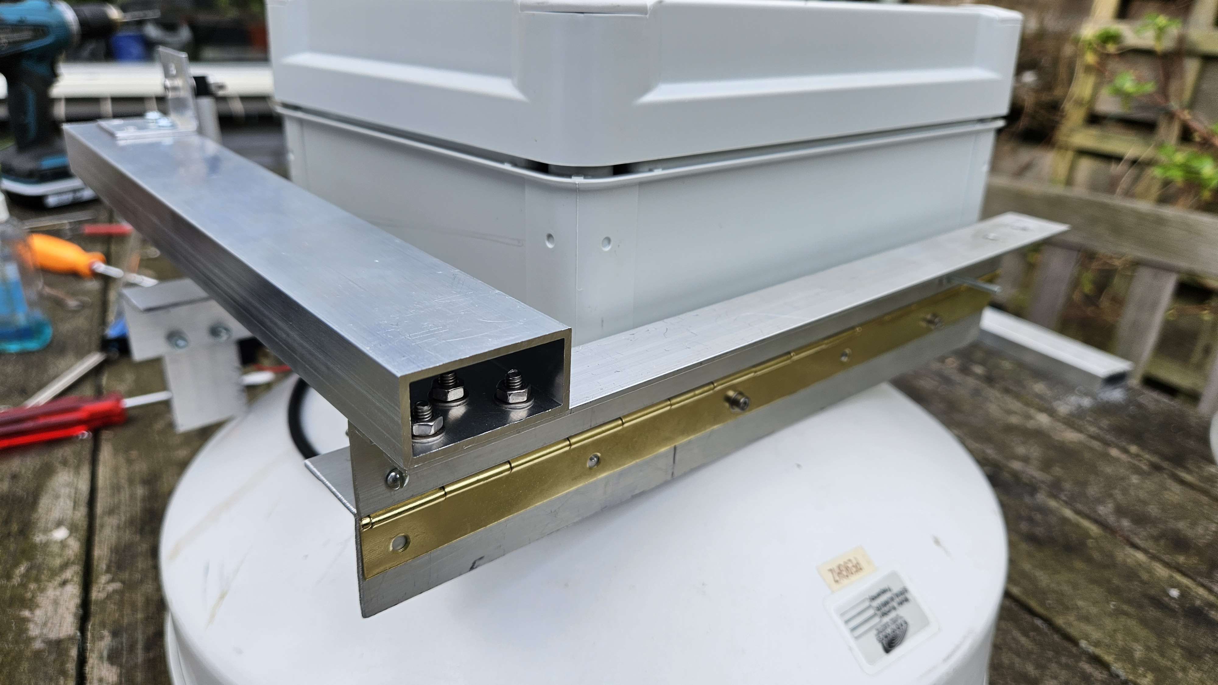
I've made the mount of the dish slightly adjustable in elevation (+ and - 3 degrees offset from horizon), by including a small actuator (12V driven) and a construction with a "piano hinge".
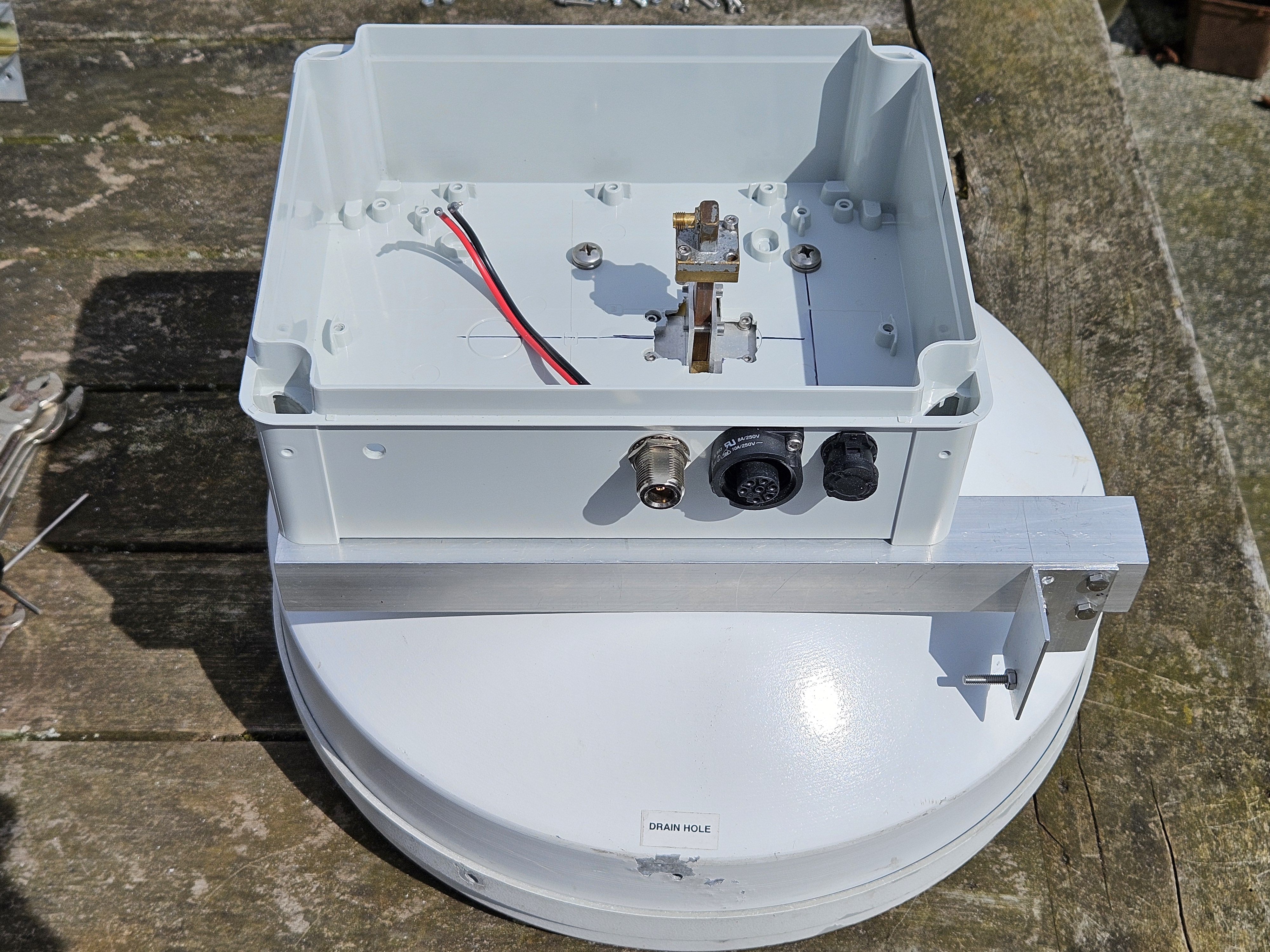
Inside the housing I've added a small (I2C) Accelerometer/Magnetometer sensor, so a readout of the elevation (and hopefully Direction) is possible. (For that and other remote-measuring purposes like PLL-lock state, Supply voltage and Current, Rx/Tx state, a little "ESP32 Devkit board" is also added in the housing). The mounted ESP32 board is shown in the later pics below.
Waterproofing the seam between housing and dish with a good amount of acid-free silicone caulk: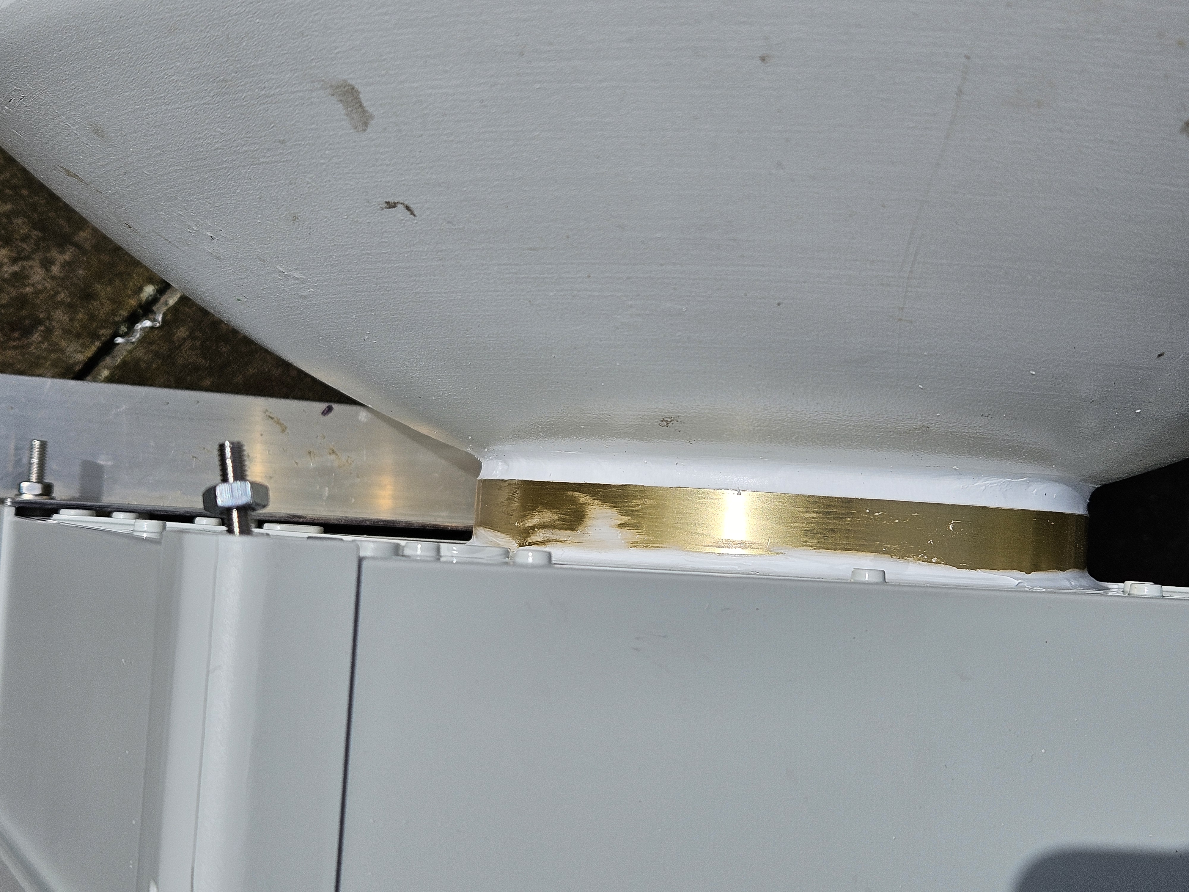
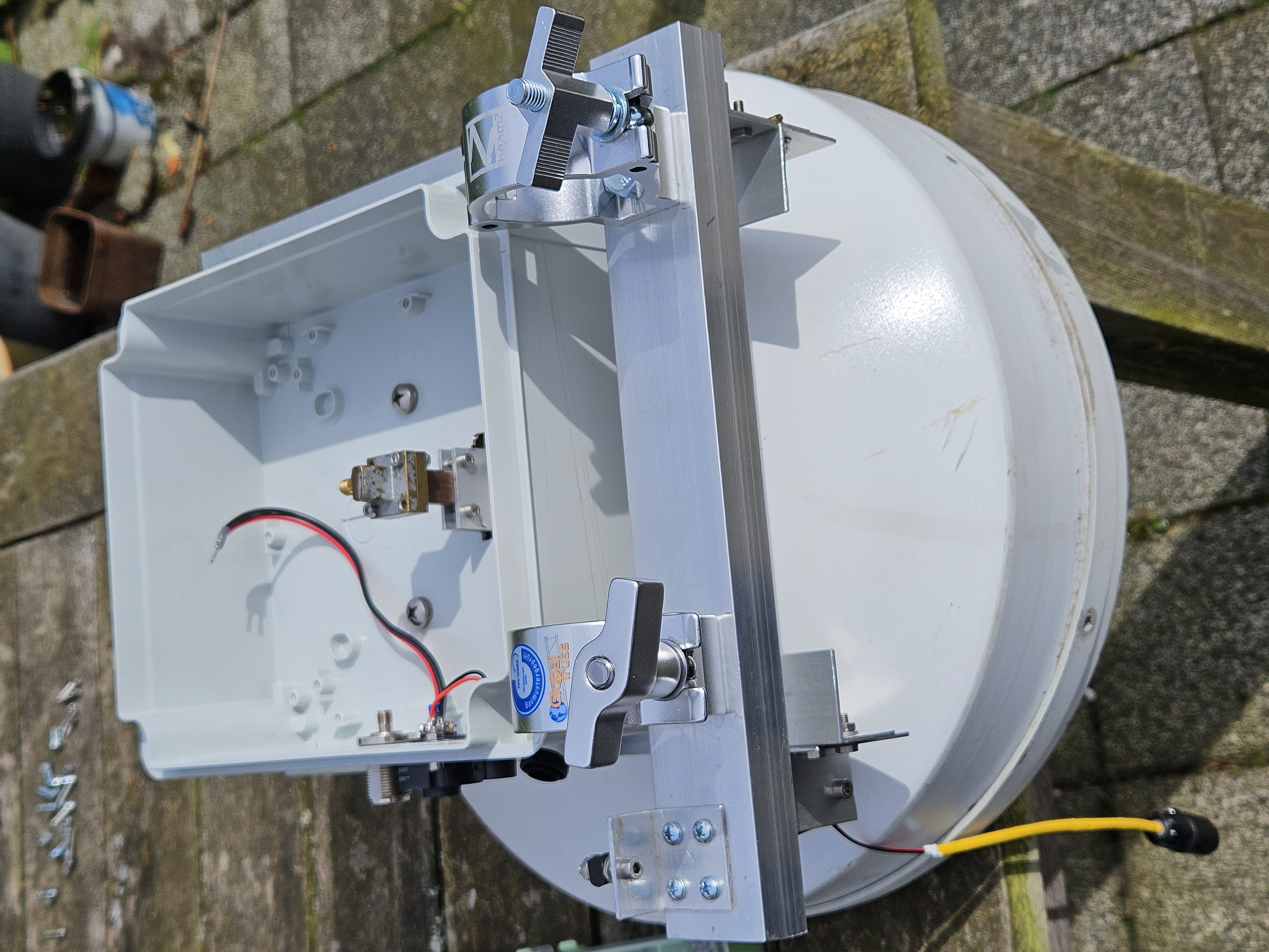
Mast-mounting with "quick fix" Truss half-couplers (as used widely in Music/ Stage / Theatre technique):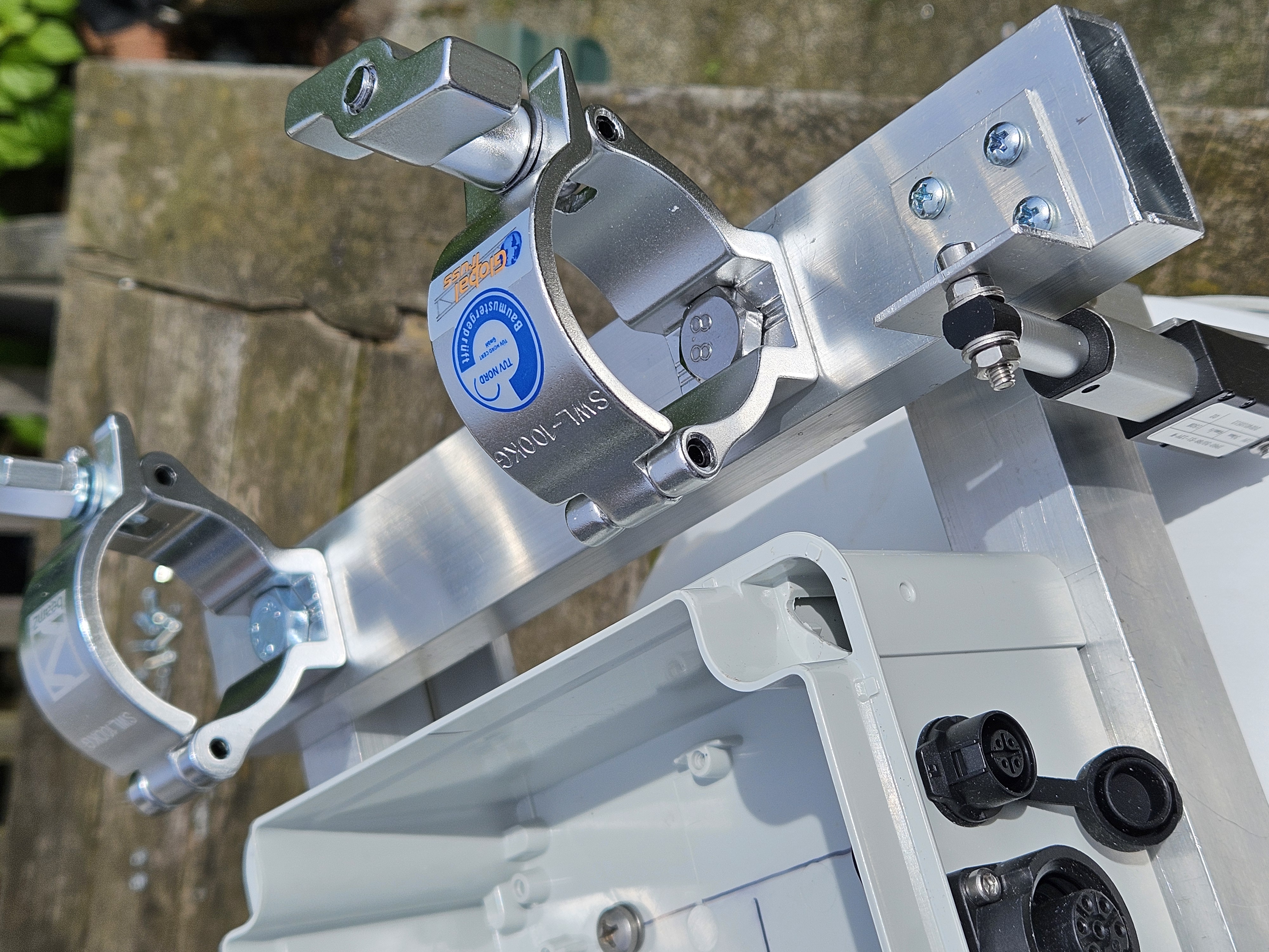
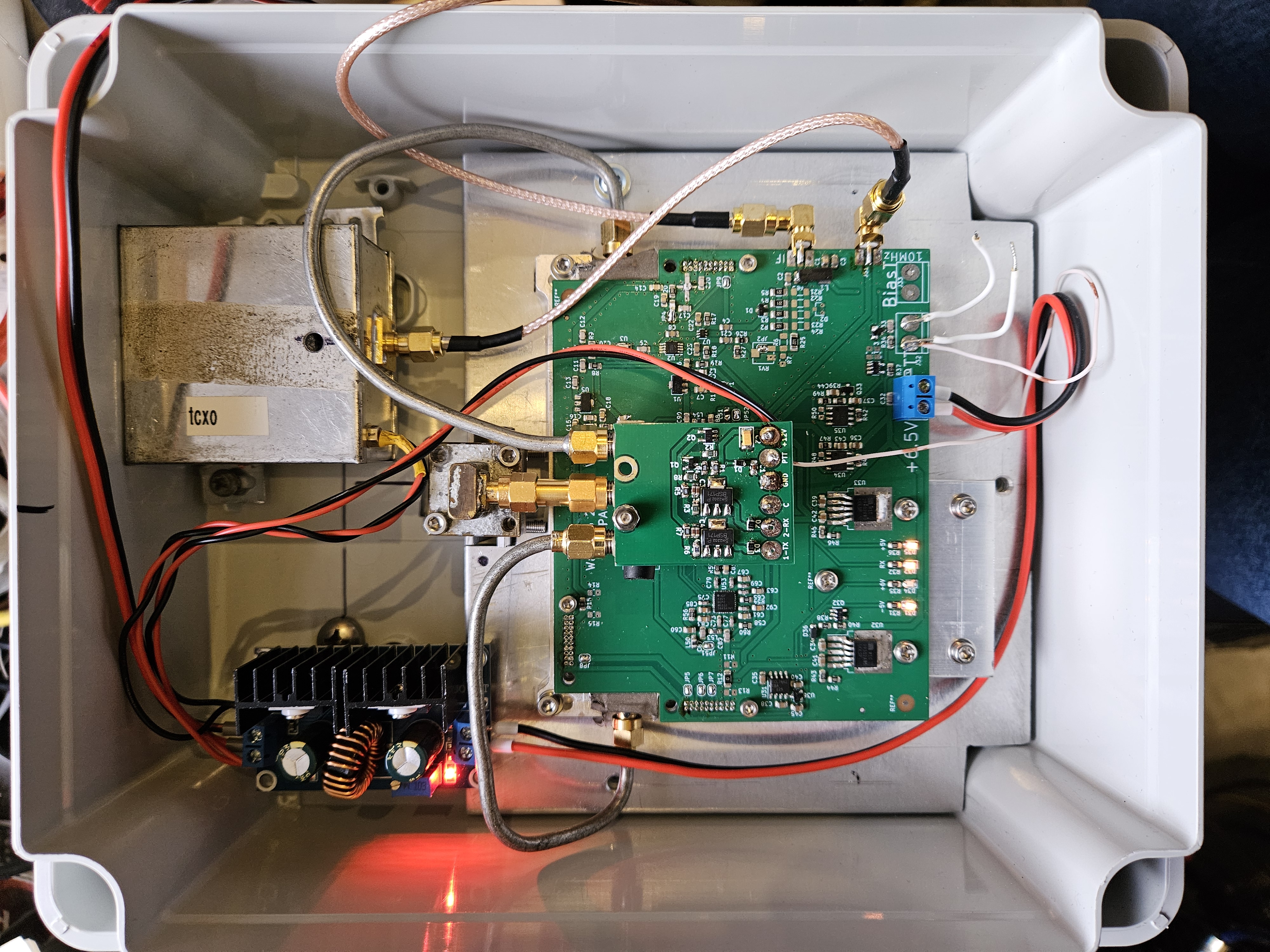
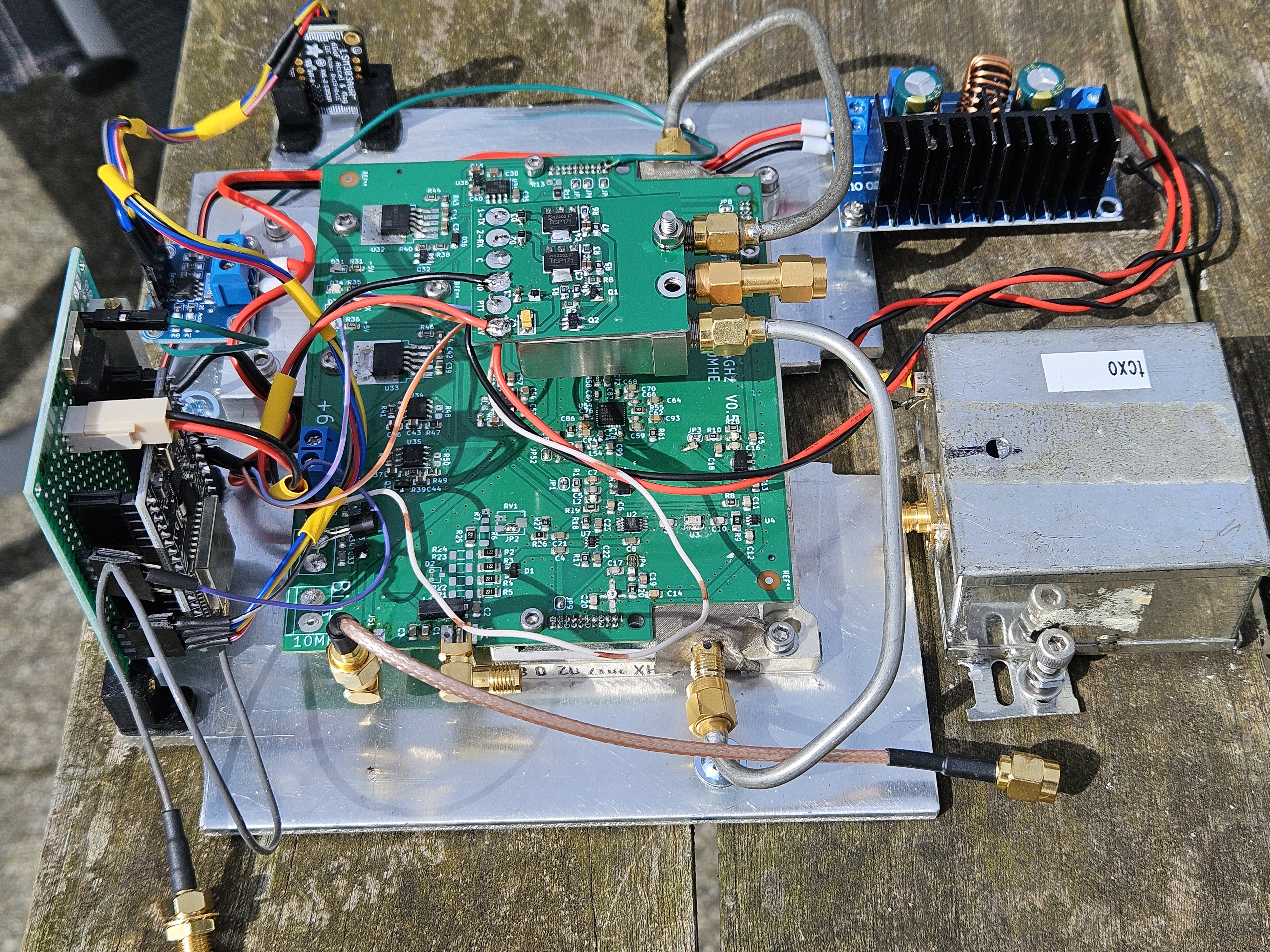
The entire transverter (Wavelab unit, add-on board) along with DC/DC converter, OCXO, coax-relay, ESP32, INA219, LSM303 sensors mounted on a 5mm strong aluminum baseplate and can be removed as-is from the ABS enclosure for ease of serviceing: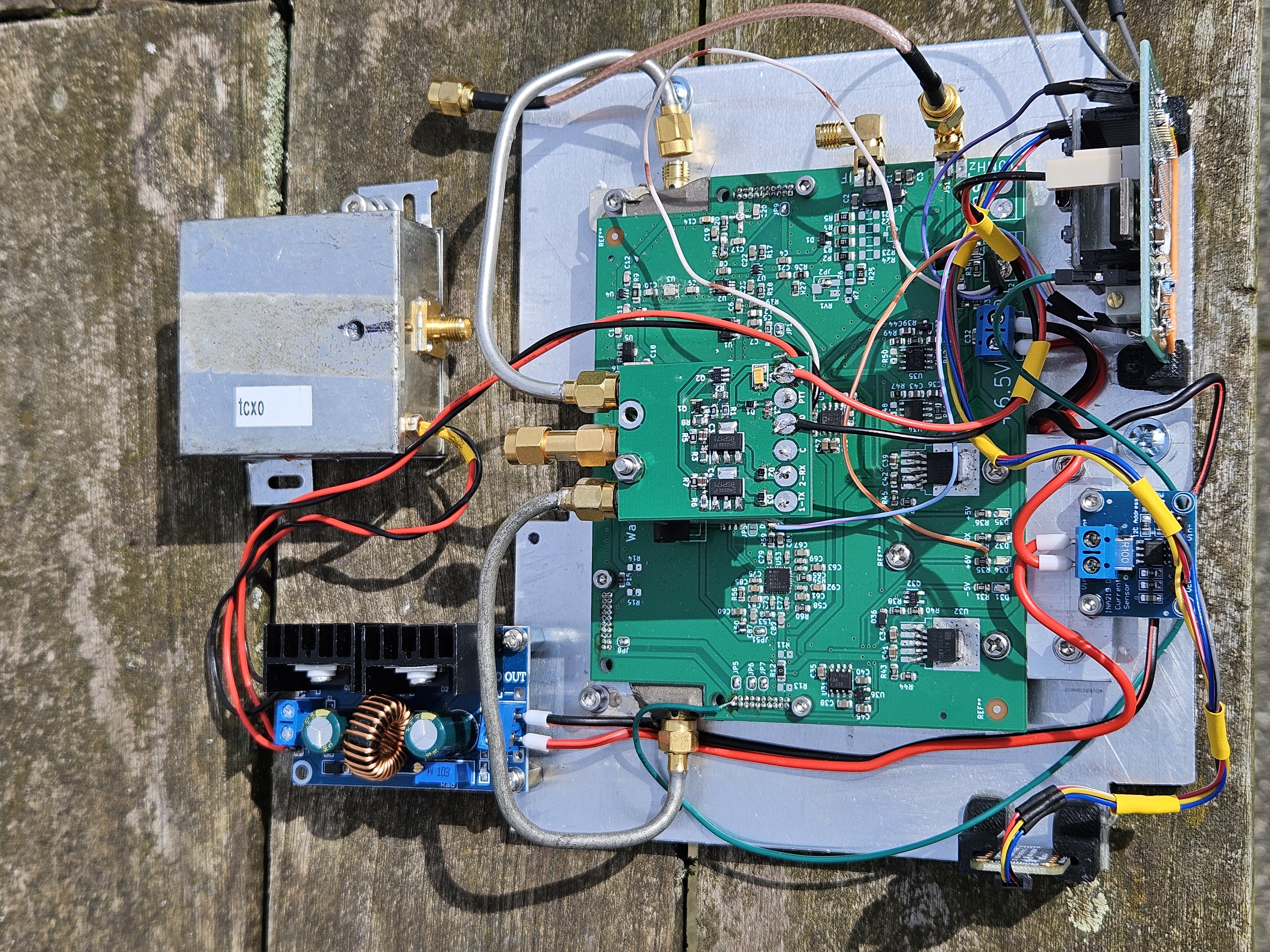
Detail of the Adafruit LSM303AGR Accelerometer/Magnetometer sensor module: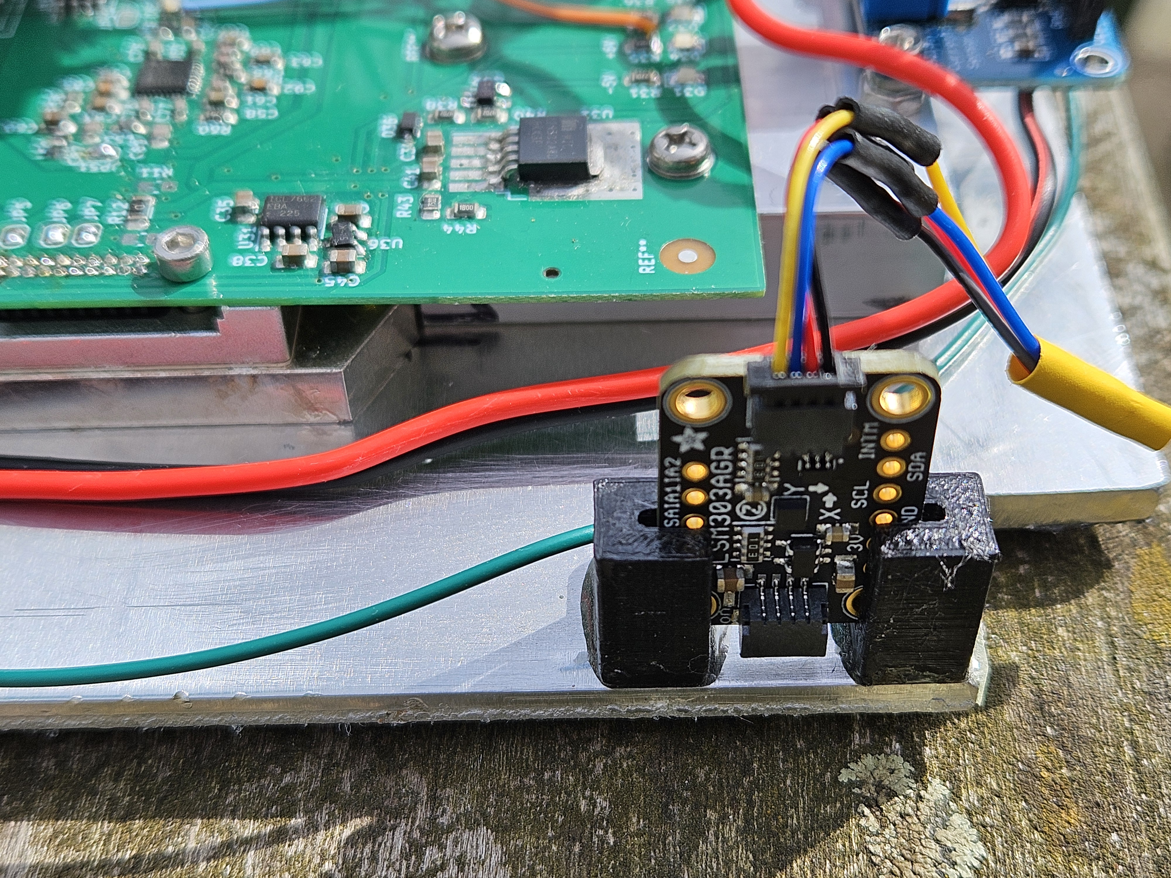
Page modified by Eddy on 2024-05-17
Previous page: 10GHz-SSPA
Next page: Miscellaneous Projects