Beacon-PLL
Small Beacon transmitters PLL locked to a (10MHz) Frequency Standard
- Small Beacon transmitters for 13 and 23cm (and 10GHz if multiplied x8).
Using SMT VCOs, small beacon transmitters can be made that are PLL locked to a 10MHZ reference standard. These lilttle beacons can be handy to check the operation of transverters and other equipment. I've obtained some MVN2330MHz VCOs (tunable frequency range +/- 2,2 to 2,6GHz) and I'm building some circuits now, using the ADF4154 (pin-compatible with ADF4002) Fractional-N PLL chip on the same PLL board as used in the 23/3cm transverters. The PLL board can be "piggyback" mounted to the rear / ground plane side of the VCO pcb.
Here is the schematic and the pcb artwork for the 2330MHZ VCO: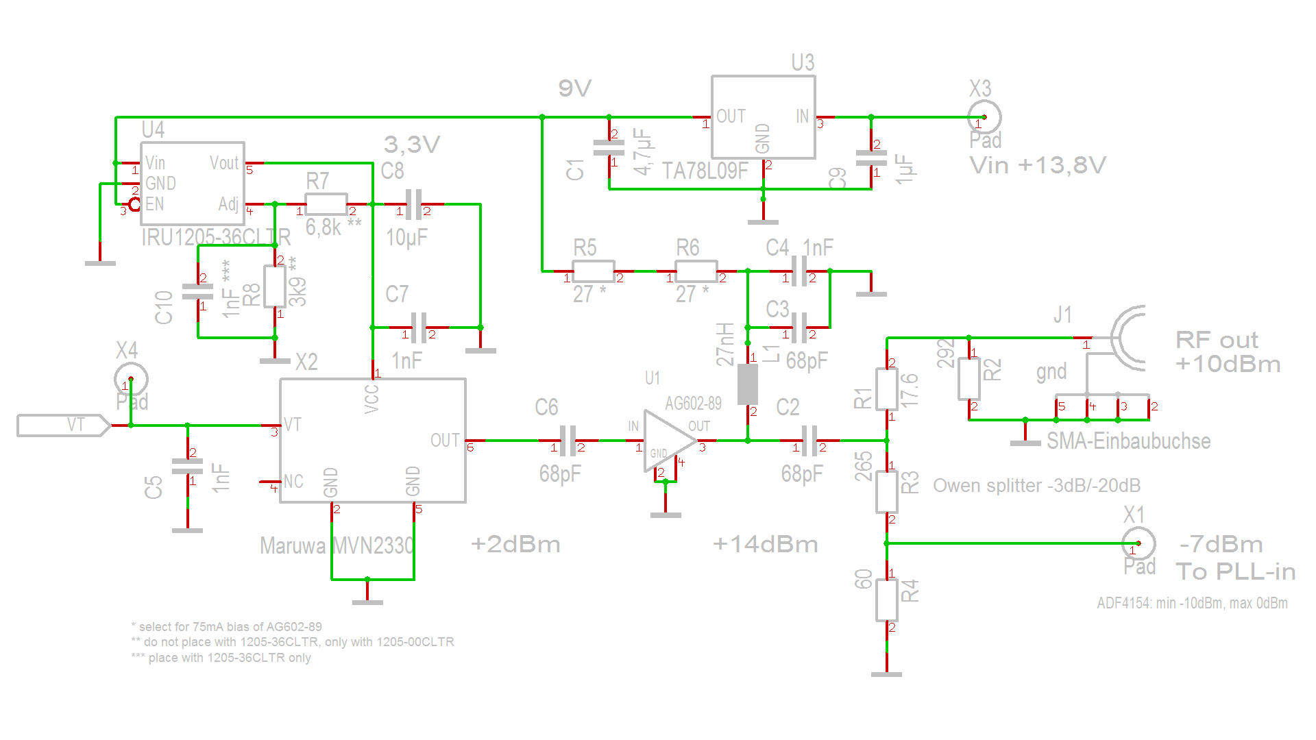
(right-click, view image in full size or download image)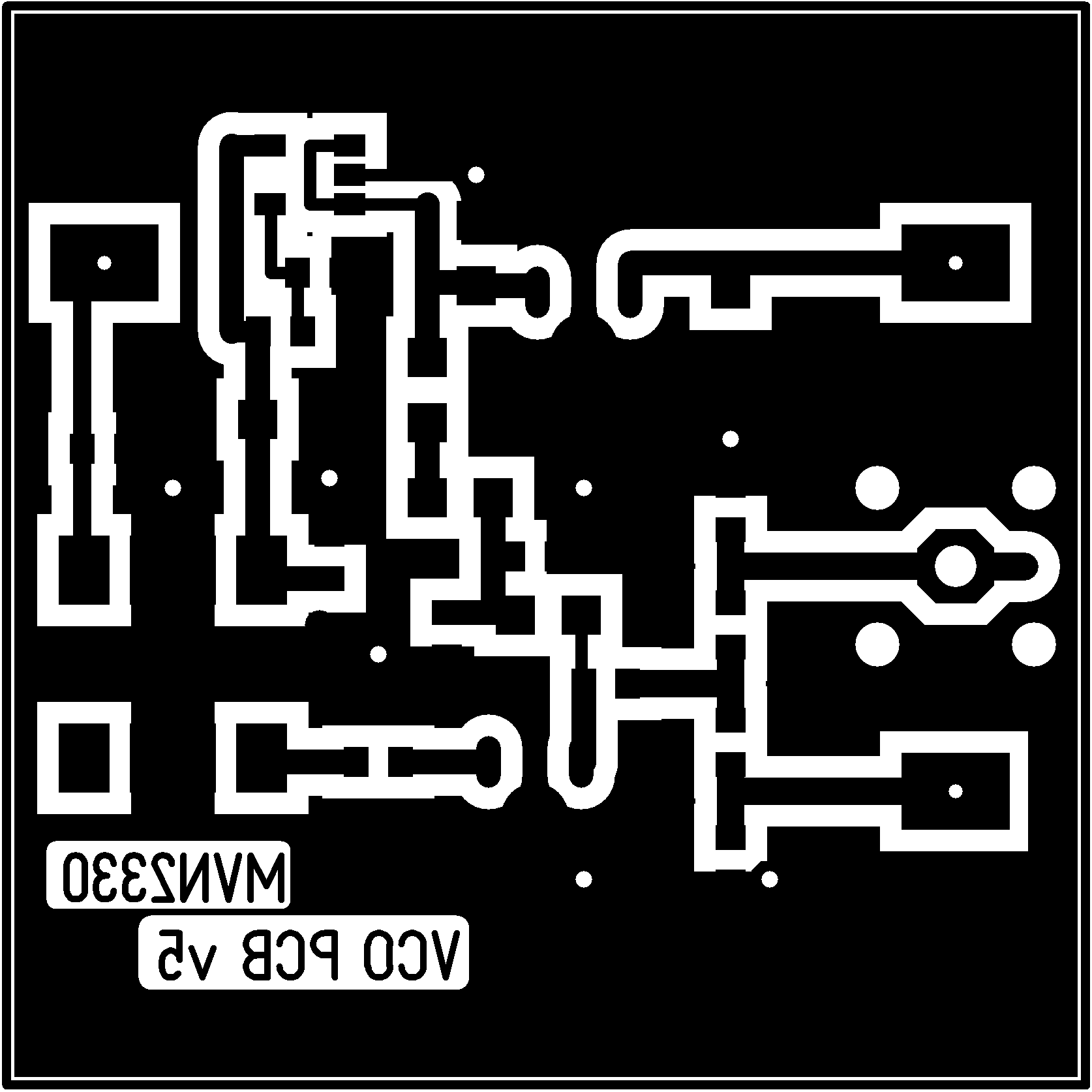

(right-click, view image to view in full size or download image)
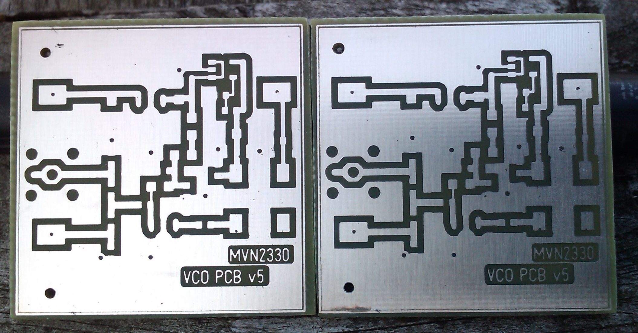
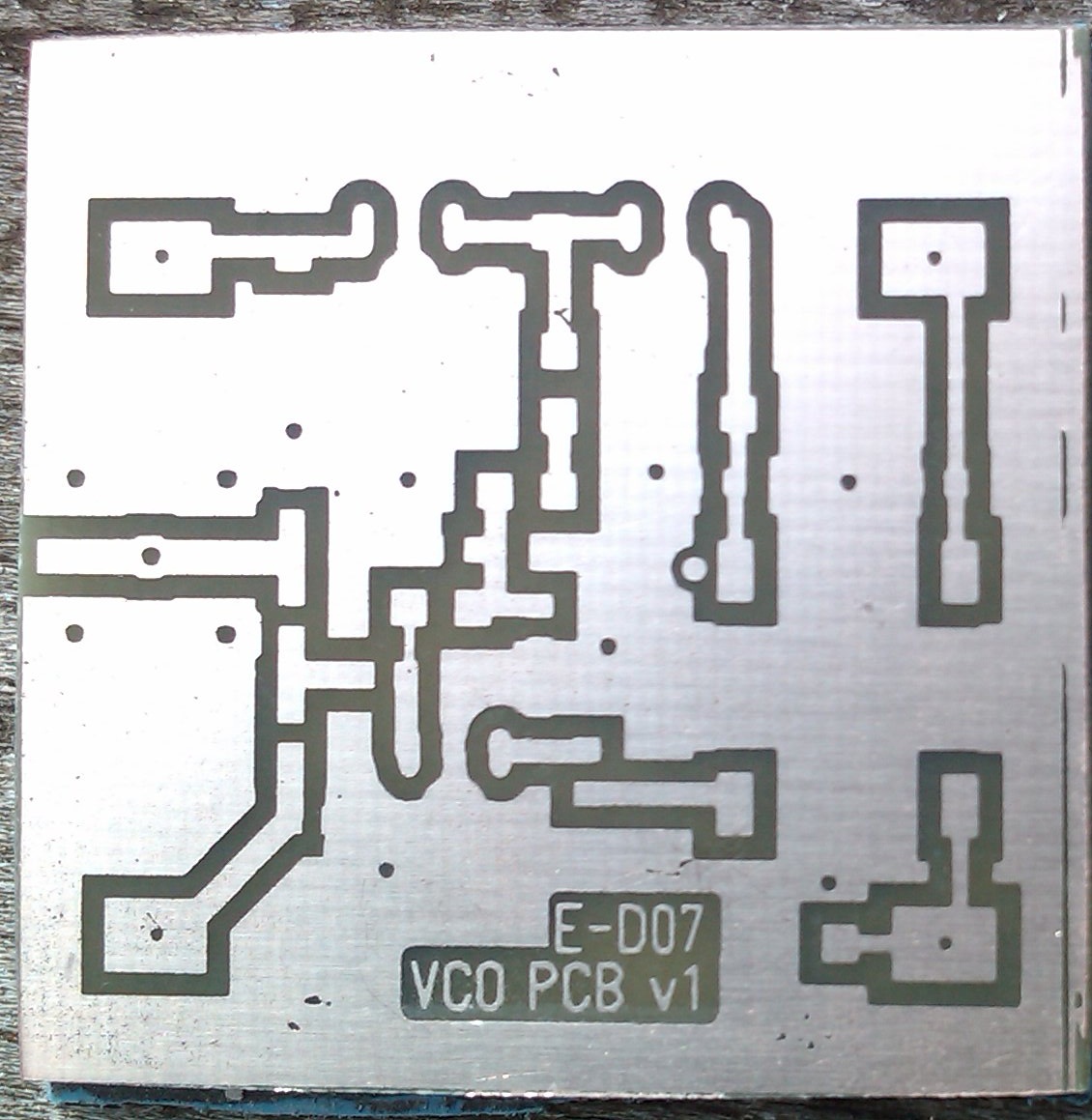
The hi-res 1200dpi mirrored pcb artwork for Maruwa MVN2330 (13cm) VCO.
Board size is 35x35mm (fits in tin-plated box 37x37mm).
I've also got some Alps E-D07 VCOs (range 1495-1850MHz ) that were modified to bring the tunable frequency down to include 1296MHz (23cm).
Here is the schematic diagram and pcb artwork for the 23cm version: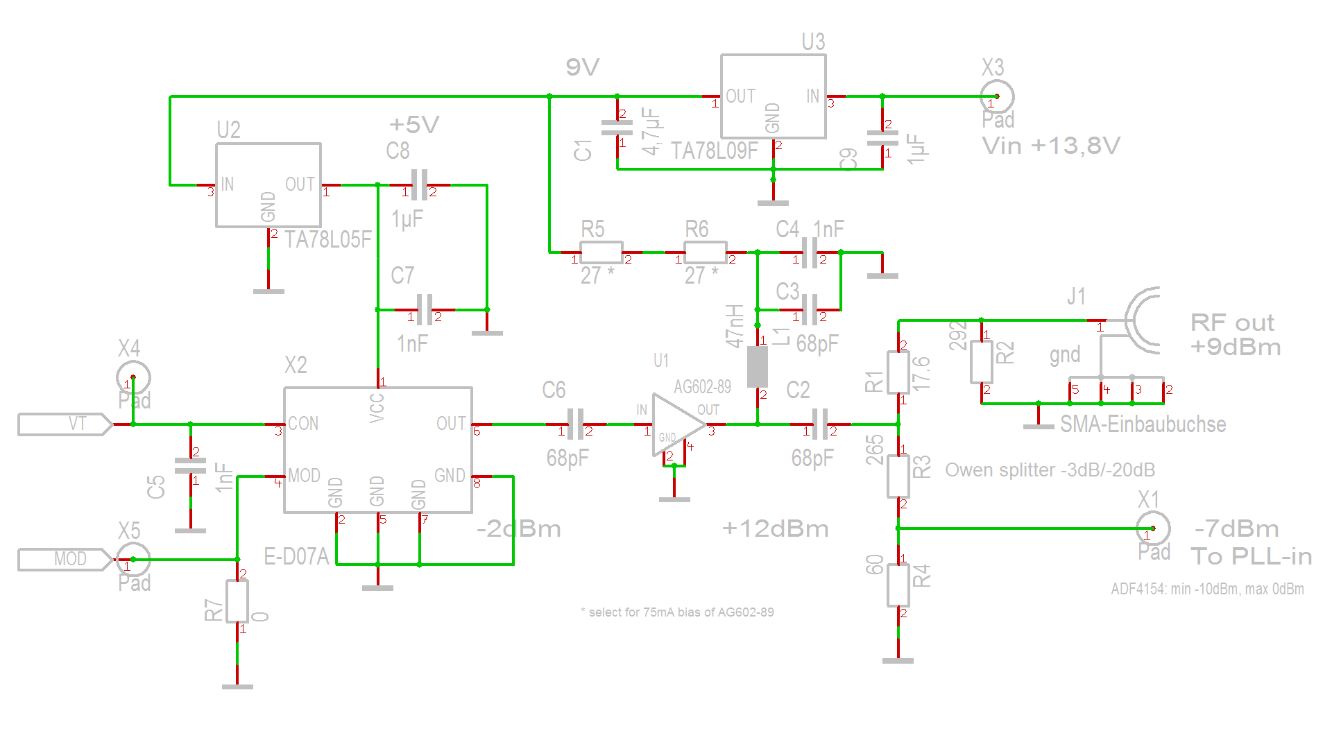
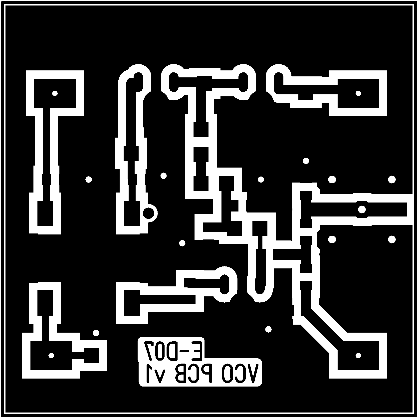
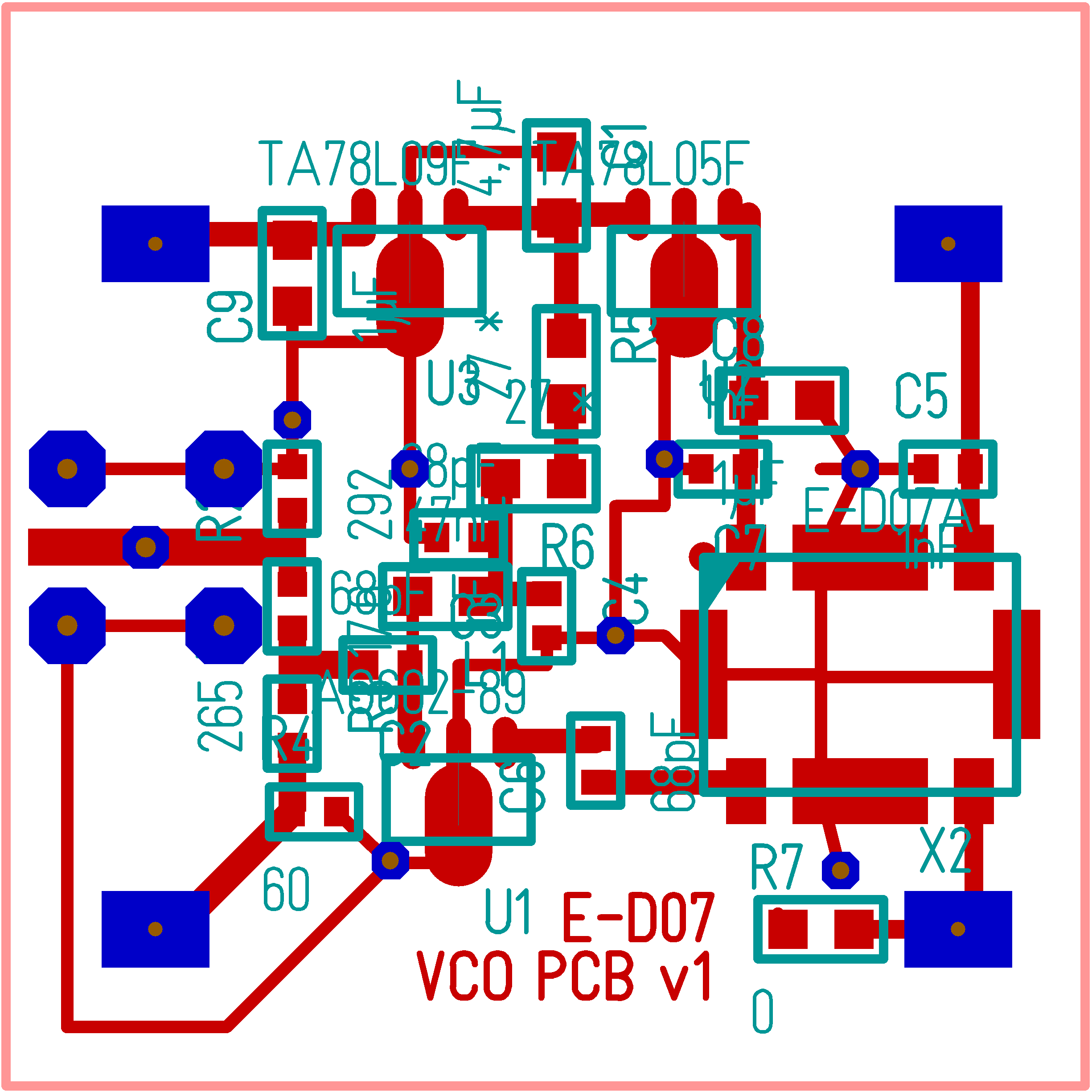
(right-click, view image to view in full size or download image)
The hi-res 1200dpi mirrored pcb artwork for Alps E-D07 (23cm) VCO.
Board size is 35x35mm (fits in tin-plated box 37x37mm).
Update 20120812:
Unfortunately, the modified Alps E-D07A VCOs don't work as they should in the 1296MHz range: They are showing sudden frequency jumps from 1295 to 1315MHz, when the tuning voltage is increased slowly in the 3,3 to 3,4V range.
Therefore I'm now waiting for other VCOs (Alps URAE8-994A) to arrive that hopefully will work better in the 1296MHz range.
Update 20120914:
Bart, PE1PFW has supplied a new batch of PLL boards, professionally made by a PCB plant, gold-plated VIAs and solder mask.
The PLL PCB hosts a small microcontroller PIC10F20x in SOT23, which initialises the registers of the ADF4xxx PLL chip upon powerup.
Here's the schematic of the PLL PCB by Bart PE1PFW: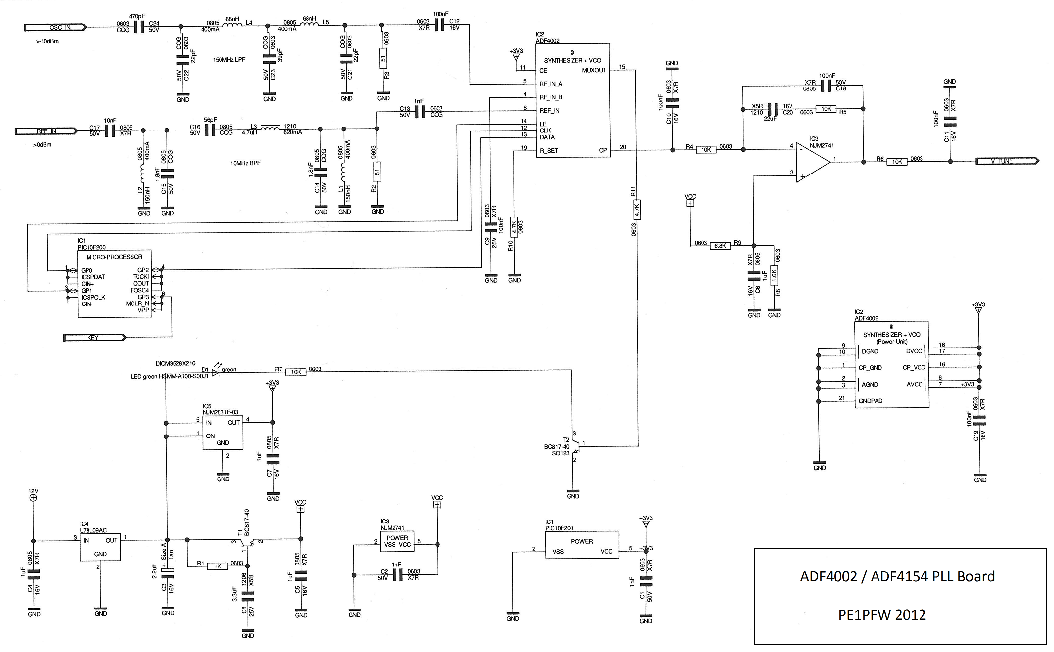
click to view image in full size or download image
Update 20120924:
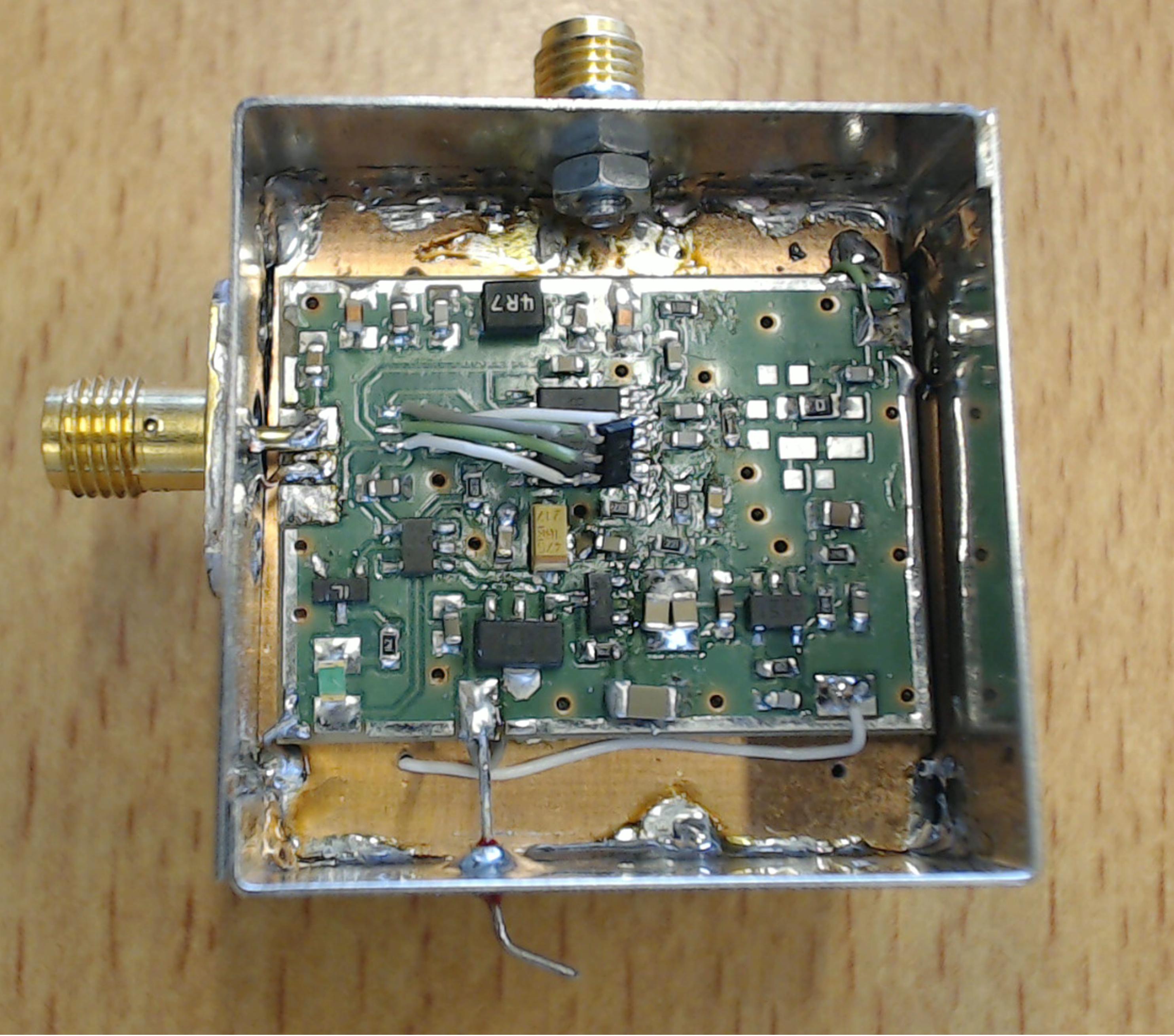
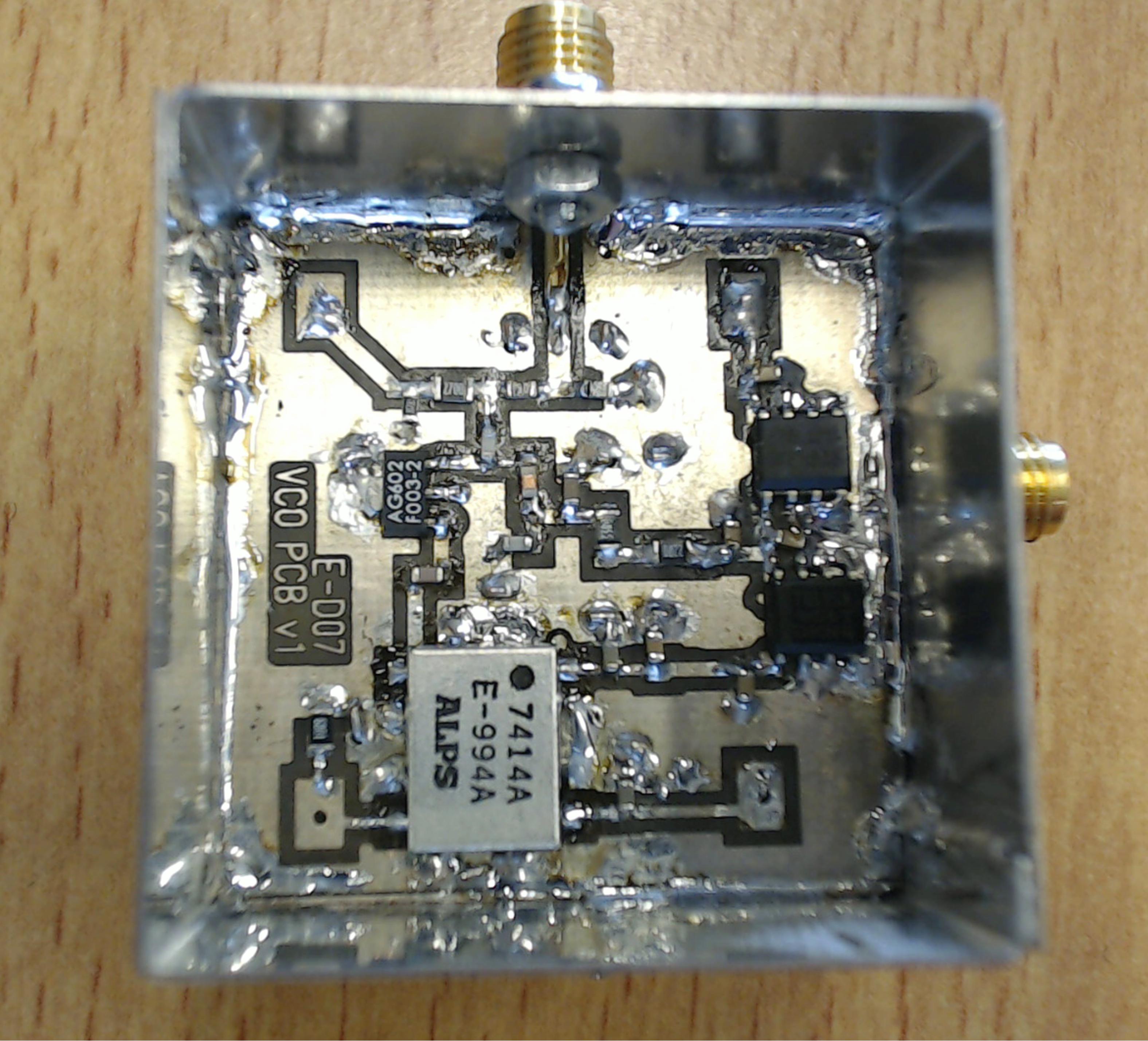
Some progress was made with the new Alps URAE8-994 VCOs. One VCO has been mounted on the VCO PCB and a PLL board was mounted "piggy-back style" on the groundplane side of the VCO PCB (see the pictures below). The PLL board was equipped with a ADF4154 chip and the controlling PIC10F200 was programmed for Fvco=1296.1006MHz (unkeyed) and 1296.1009MHz (keyed).
Output of the VCO PCB (at +8.4dBm) was fed via a 20dB pad into a x8 multiplier (based on a Hittite HMC444LP4 chip). The multiplied output (+6dBm) at 10368.8048MHz / 10368.8072MHz was fed into a waveguide transition followed by a 20dB waveguide attenuator and finally a small (14dBi) horn antenna. The beacon was keyed by a simple PIC16F84-based cw-keyer, that I made long ago for the PI7GOE beacon.
The signal was received by my 10GHz transverter at a short distance (with its waveguide pointed away from the beacon antenna, in a direction where the signal was relatively weak to avoid overloading the RX).
The keyed beacon signal sounds like this:
Update 20120928:
For a quick test, I placed the beacon with a small 14dBi horn (output estimated at 20dBm EIRP) behind a window on the first floor (4m above ground) of the PI4Z Radioclub building, pointing towards my home QTH. Then, from my home QTH at 6km distance, I was able to receive the beacon signal using my 10GHz transverter placed in the attic (inside, below the roof at 9m above ground) with a 18dBi horn antenna. It was just readable above the noise, listen to audio:
Update 20120930:
For a second test, I've now built the small beacon in a water-proof housing (left over from the old PI7GOE beacon) that has on top a waveguide slot antenna with 2x 18 slots. This contraption is mounted in the antenna-tower on top of the PI4Z Radio club building at a height of 9 meters above ground level. The gain of this omni-directional Waveguide Slot antenna is estimated at approx. 16dBd (or 18dBi), so the beacon now has an output power of 24dBm EIRP. Now the received signal at my home QTH improved slightly, it is now clearly above the noise.
If you receive the beacon on 10368,805MHz please send your reception report to me.
Below are some photos of the PCBs: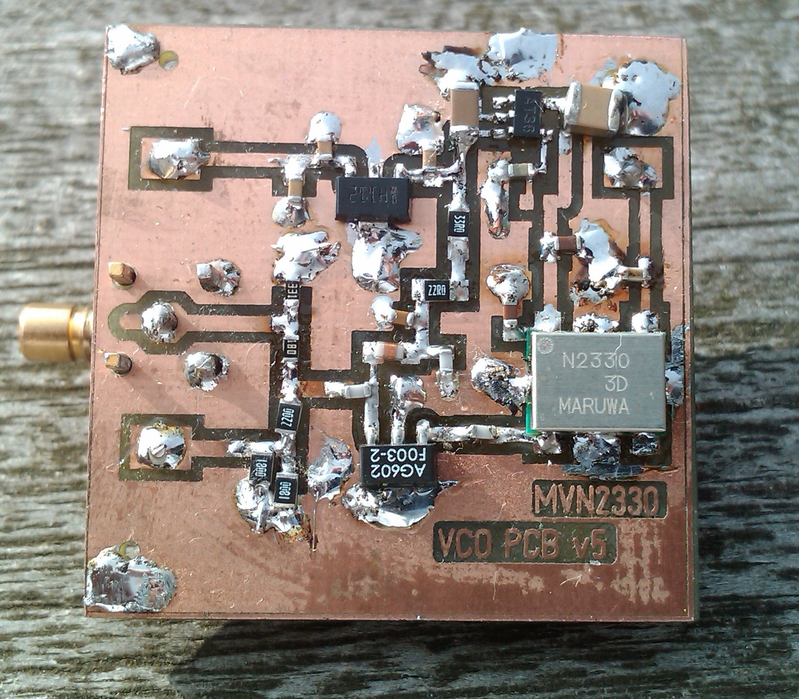
Permission is granted to reproduce PCBs for personal / amateur radio / non-profit use only.
Any commercial use without prior permission from owner prohibited.
Page modified by Eddy on 2013-09-18
Previous page: LO PLL locking
Next page: 1,3+ 5,7 + 10 + 24GHz Personal Beacons PE9GHZ/B