Station equipment
(*this page is still under construction *)
Main rig:
- Icom IC-706MkIIG, equipped with additional narrow SSB and CW filter
HF - 50 - 144 - 430 All Mode - Yaesu FT221R 144MHZ All Mode (owned since beginning of my Amateur Radio career in 1978), now retired. But still occasionly used as IF rig behind a SHF transverter. SOLD
- SDR:
RTL E4000 Dongle
Funcube Dongle Pro plus
LimeSDR-Mini
ADALM-Pluto
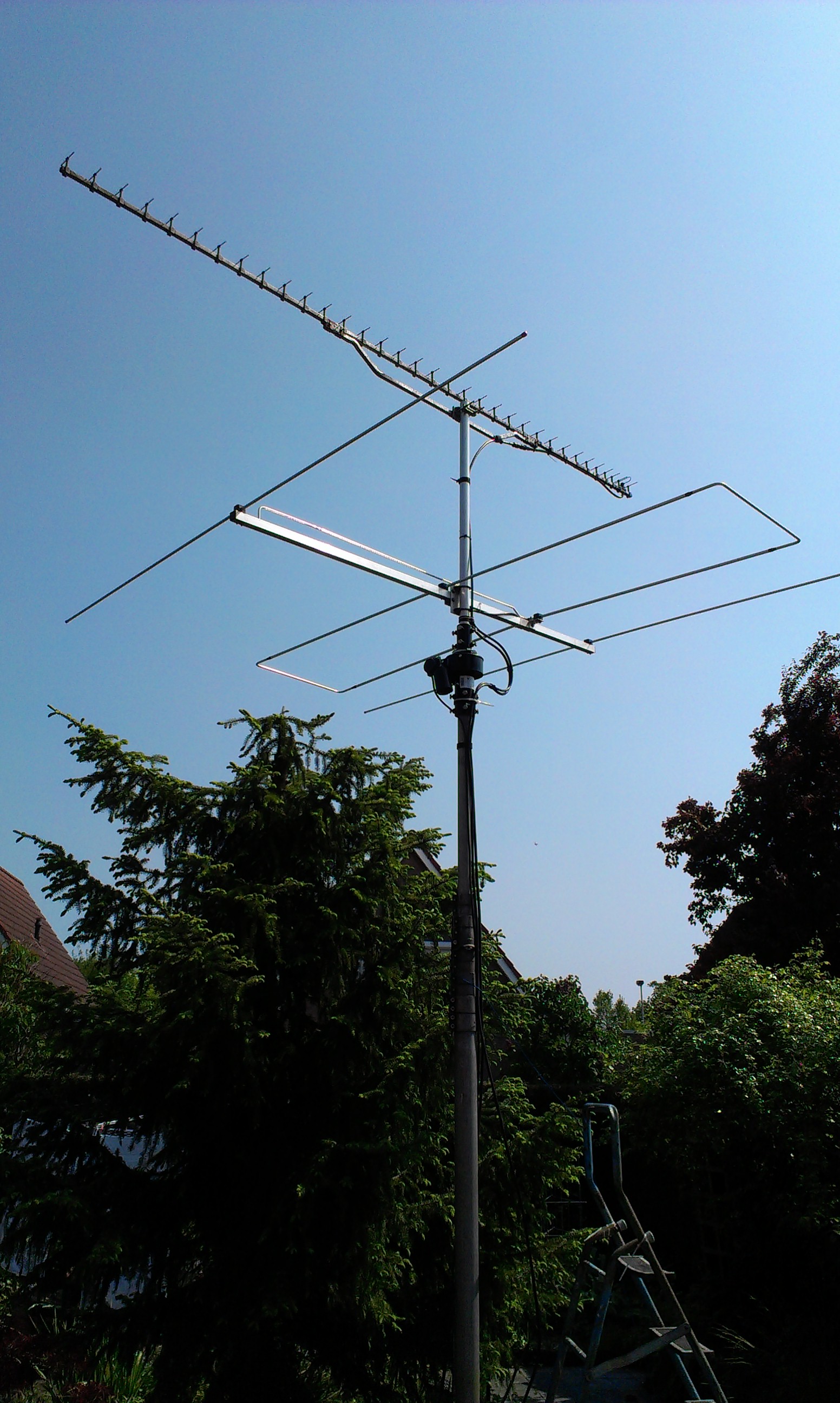
Tower: A small telescopic mast in my backyard, with a AlphaSpid RAK rotator which turns my 3el LFA-50MHz and a 35el FT9FT for 23cm. Top-Height usually restricted to 5m (not very good for SHF).
1,3 GHz station:
- DB6NT transverter (1,5W out) DUBUS 1992/04 (local copy)
1152MHz LO modified for PLL locking to a 10MHz reference - M57762 Power module (14W out)
- Antenna: 35el F9FT Yagi at +/- 6-8m asl (on telescopic mast)
- Feeder: 1/2 inch Flex, 10m long.
- 120W SSPA with 2x MRF286
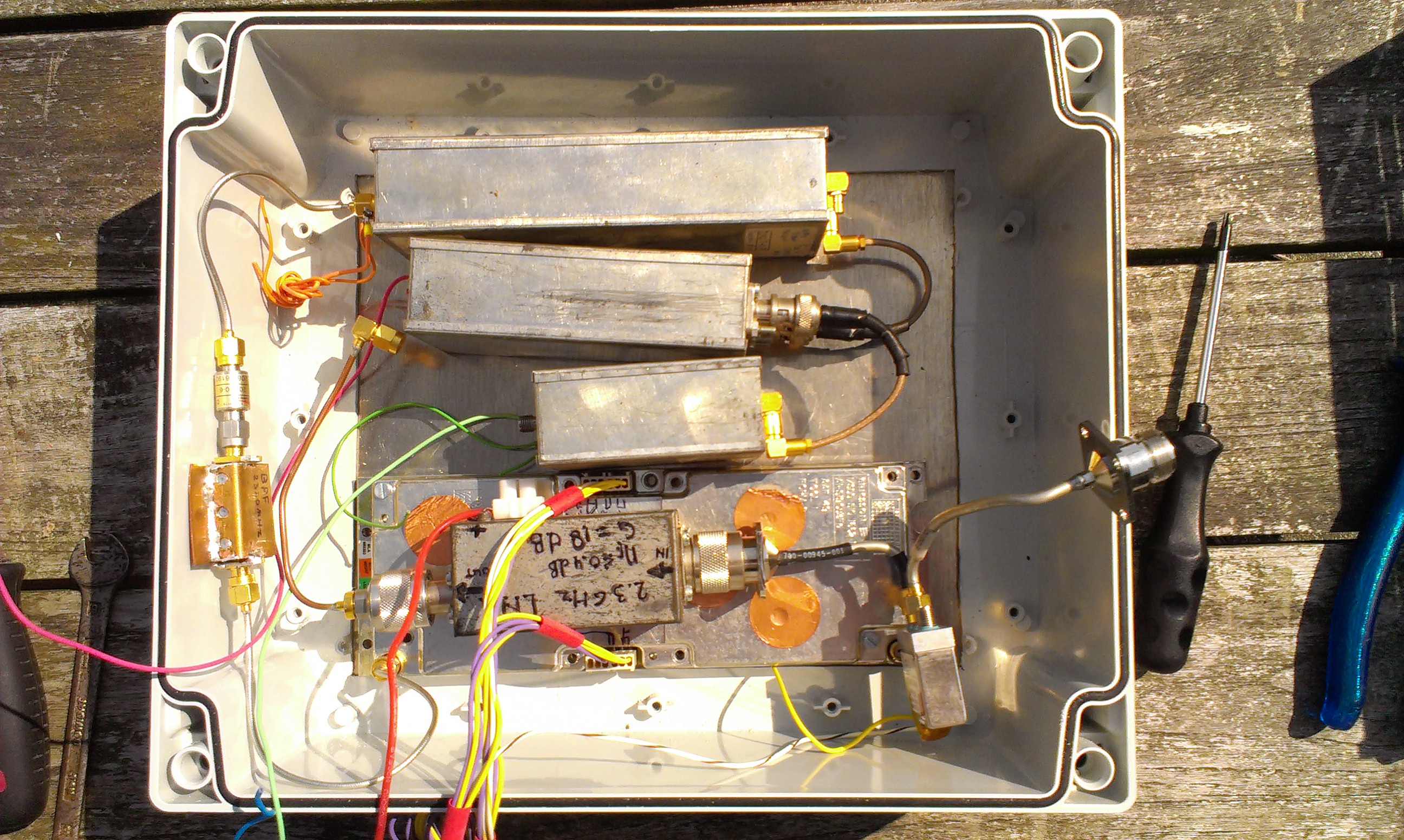
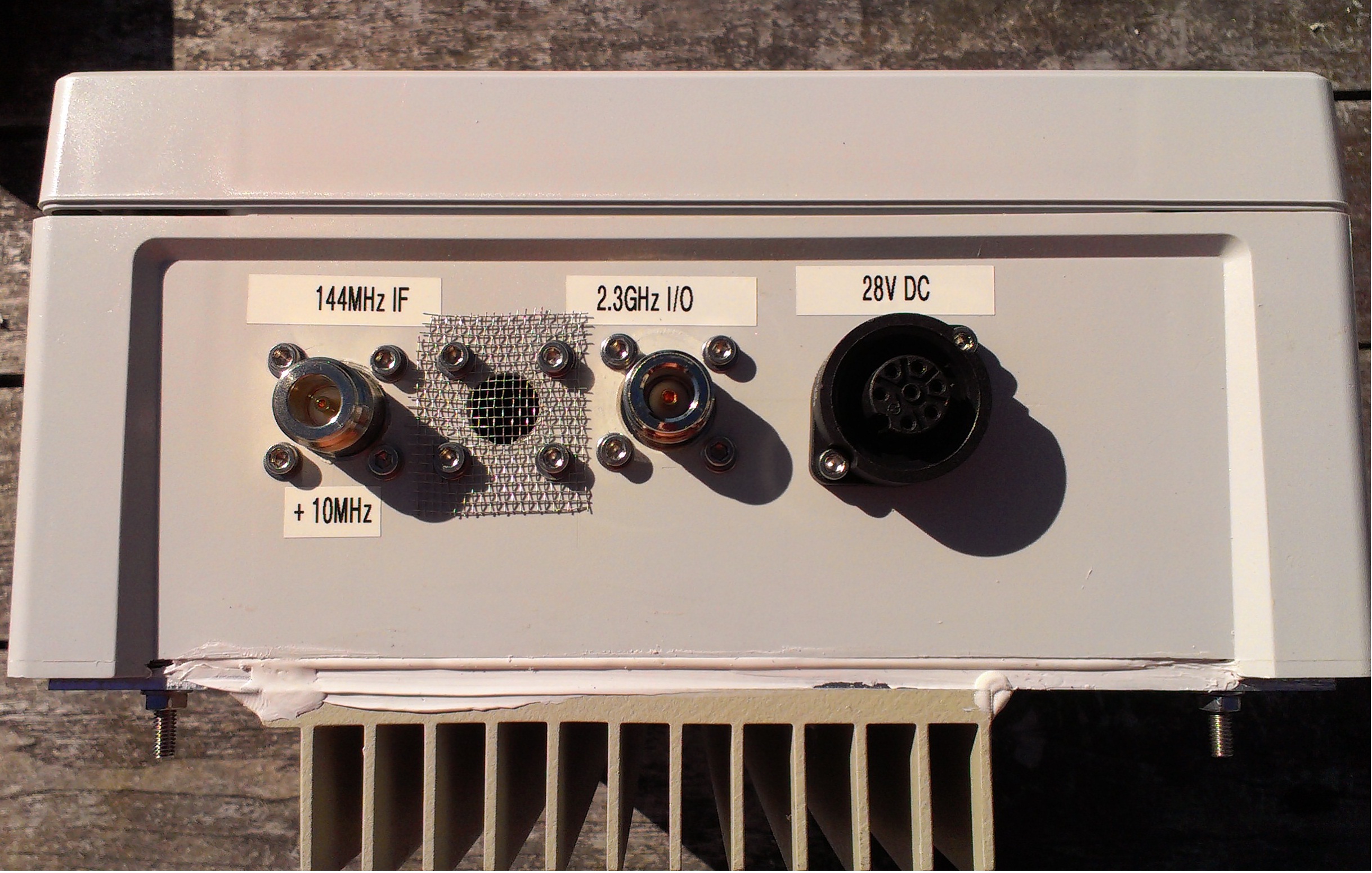
2,3 GHz station:
- 144MHz - 2320 MHz transverter (modules built from the book: UHF unterlage Teil V)
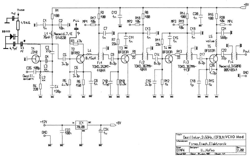
- X5T2176-P 2176MHz local oscillator module (schematic) (modified for PLL lock to a 10MHz reference) (UHF unterlage Teil V p. 946)
- TSM2/13-0,1P 2m/13cm transmit mixer (DD9DU) UHF unterlage Teil V p. 891
- TEM13/2-1,9dB 13cm/2m receive mixer (DD9DU) UHF unterlage Teil V p. 865
- PA-driver with 3 x BFQ68 (DK2UO, UHF-Unterlage Teil IV, p. 634) -no longer used-
- PA-driver 2W DB6NT 11.96 -no longer used-
- MT2.3 E 10W Lineair (kit, DL2AM) -no longer used-
- (04/2013) Ericsson 40W (46,5dBm) sspa with 2x Motorola MRF 21030 (Many thanks to Bart!)
- -40dB Directional Coupler in UT-141 Semirigid, with AD8319 and ADL5902 log power detectors for Output power and Reflected power measurements.
- HEMT-LNA (Nf < 0,4dB) with NE32548, design by DJ9BV (DUBUS).
Update 31/07/2013: Re-housed the complete transverter in a Fibox IP68 ABS housing, to enable mounting in tower close to the antenna. Waterproofing finished.
Some pictures of this re-housing work:
 Trying best fit of all parts in box.
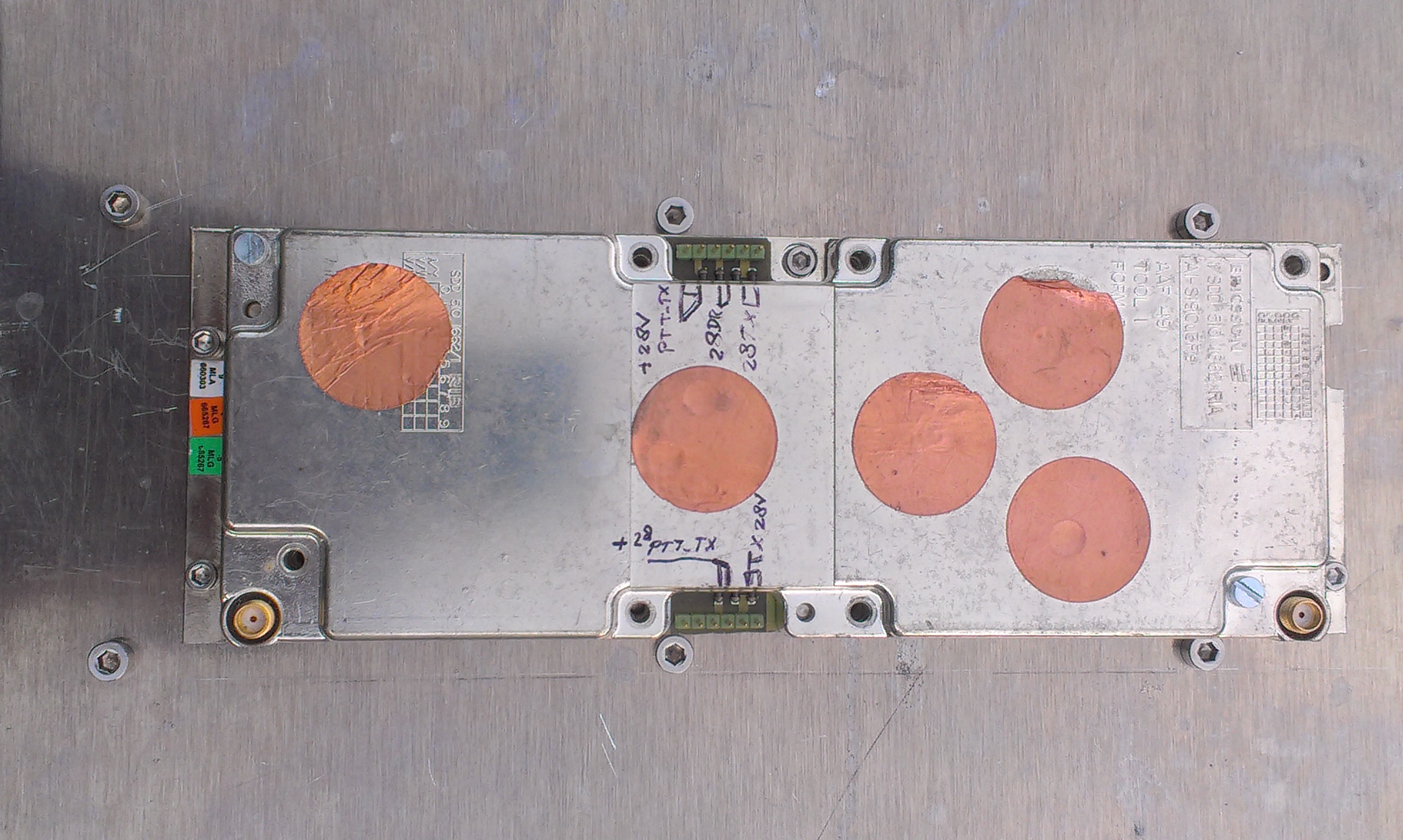 SSPA bolted on bottom plate
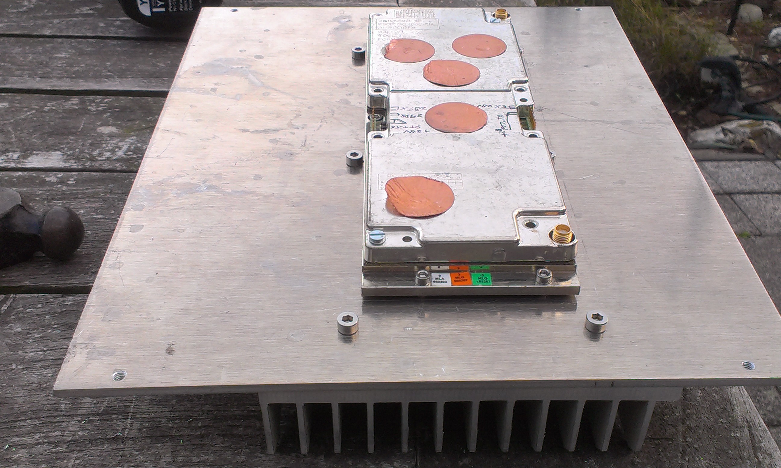 SSPA on bottom plate with heatsink on outside.
 Bottom with all connections.
Note the venting hole covered with fine mesh to prevent insects from entering the box.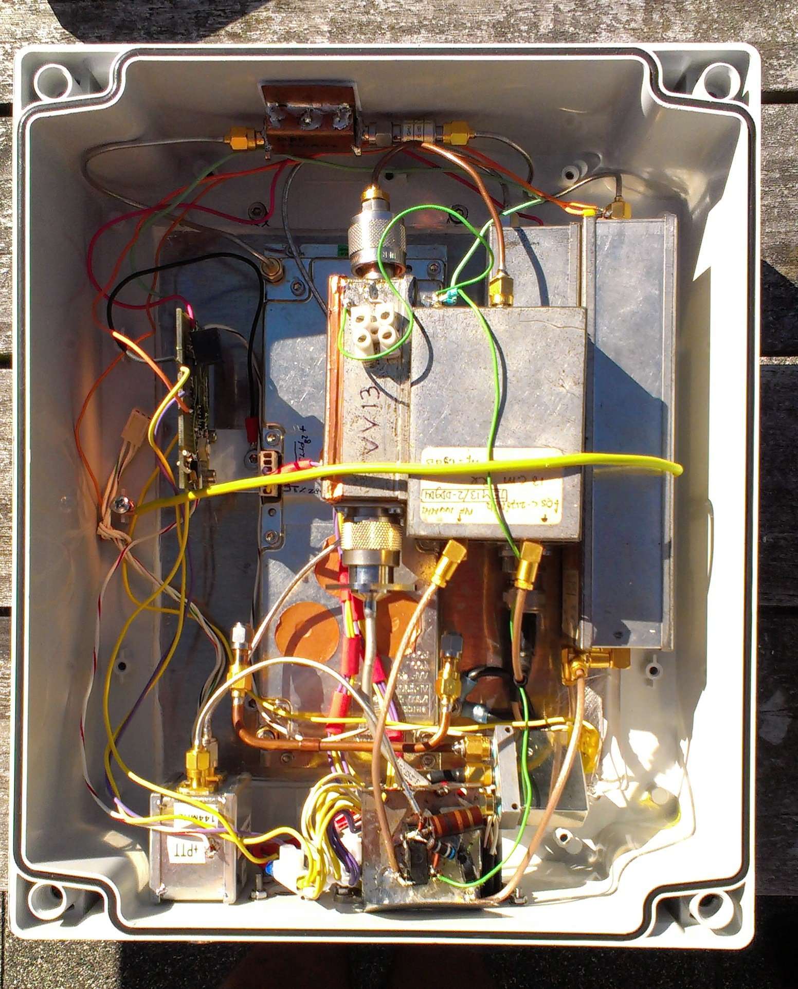 Inside the transverter box.
Sequencer PCB and IF input circuit are still prototypes..
10 GHz station:
- 2,556GHz LO chain (modified for 10MHz PLL lock)
- 106,5MHZ OCXO DF9LN (no longer used since LO is now PLL locked to 10MHz reference)
- Transverter: DB6NT Dubus 1991/01 (local copy)
- 200mW Power amplifier Dubus 1991/01 (local copy)
- Modifications 10GHZ transverter and Power Amplifier Dubus 1991/02 (local copy)
- MT10-E3W linear amplifier DL2AM
- Antenna: 20dB horn mounted directly on transverter box, when used at home QTH (pointing out the window in the attic).
60cm prime-focus dish with Krommhorn feed, when used at PI4Z Radio Club
Currently I'm preparing a second 10GHz station, for permanent use at PI4Z club.
Power amplifier: 37dBm with < 10dBm input (ex. TV broadcast link).
24 GHz station:
To be able to receive the 24GHz beacon, Bart pe1pfw has lent me a small transverter.
This consists of a DB6NT MKU LO 12 PLL (option 02) and a 24GHz MK3 transverter module with waveguide bandpass filter and a 24GHz LNA.
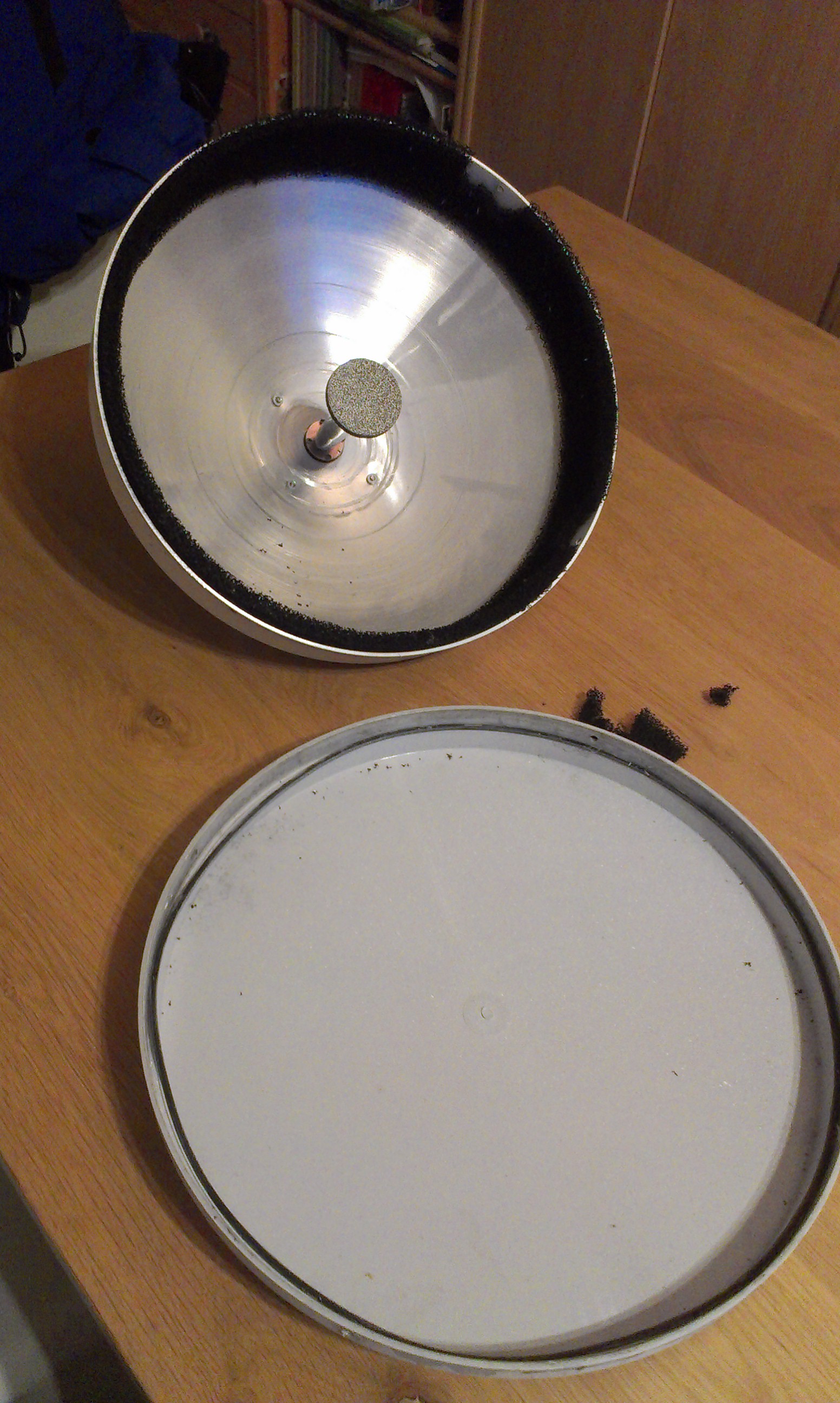
Antenna: 33cm prime-focus dish (former 38GHz telco link). To use at 24GHz, a simple penny feed on the end of a piece of WR-42 will be made.
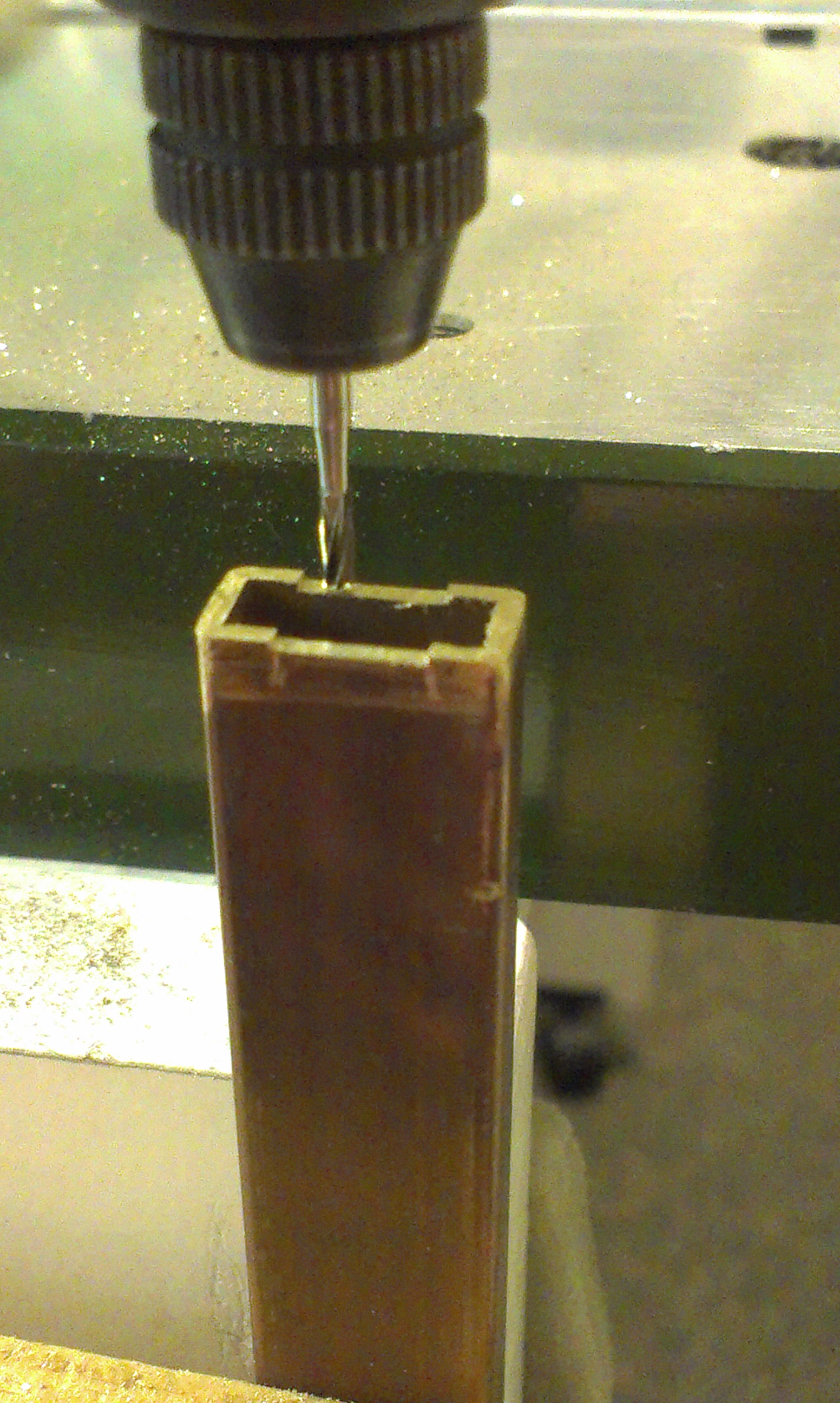
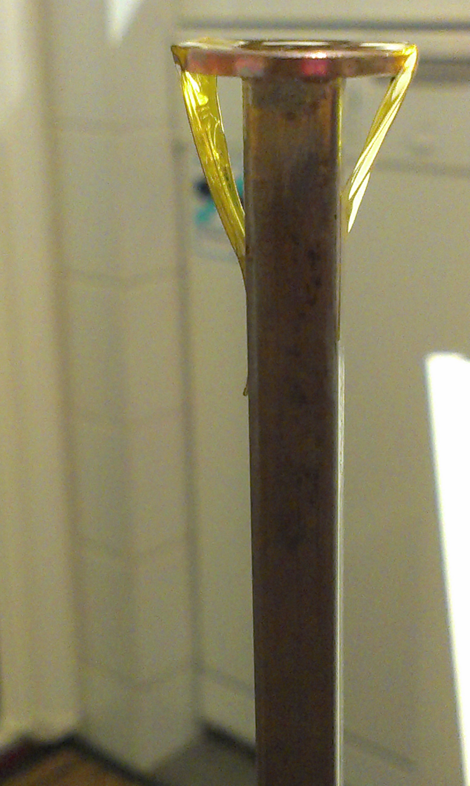
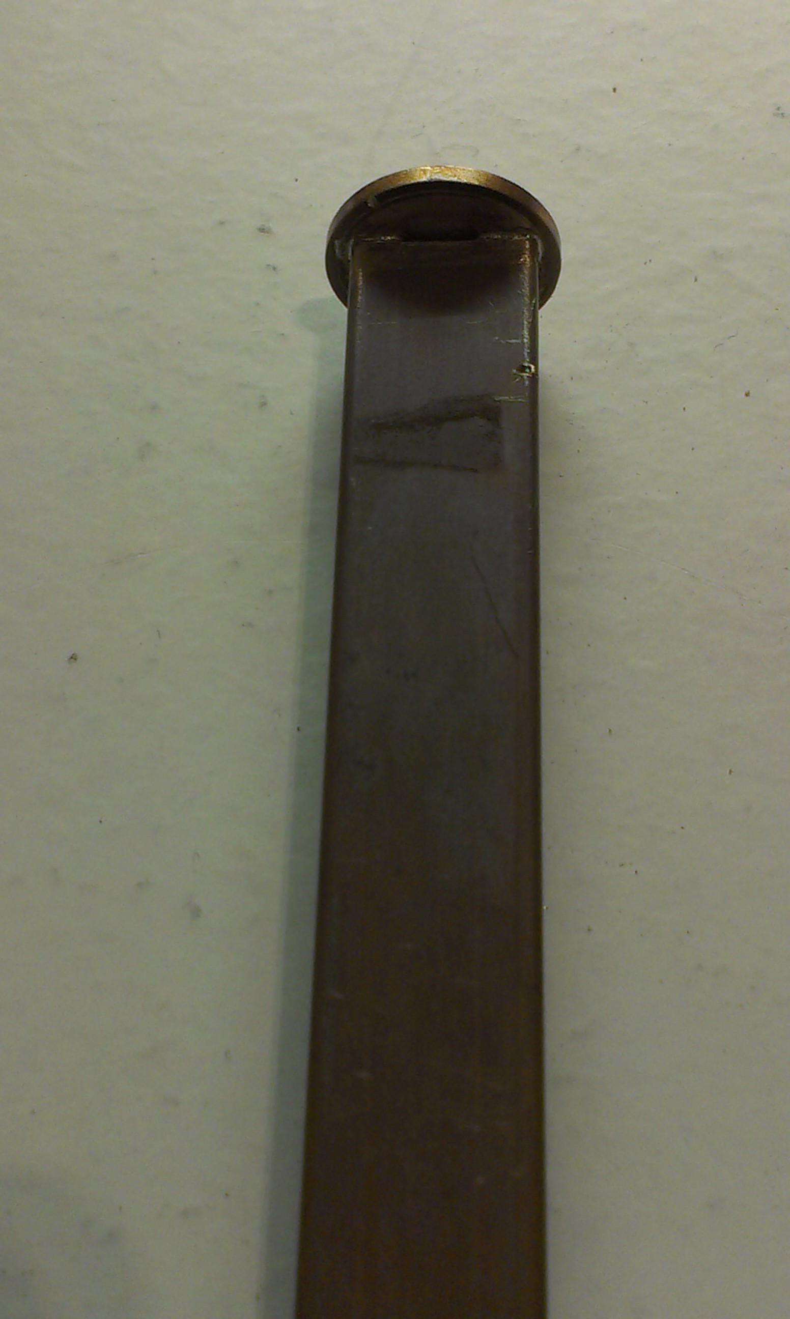
Construction of a Penny Feed for 24GHz dish:
Milling 6,2 x 0,5mm slots in the wide sides of one end of a piece of WR42 waveguide. Then solder a 1-Eurocent coin to the waveguide, using solder-paste and a hot-air gun. Kapton tape was used to hold it in place while soldering.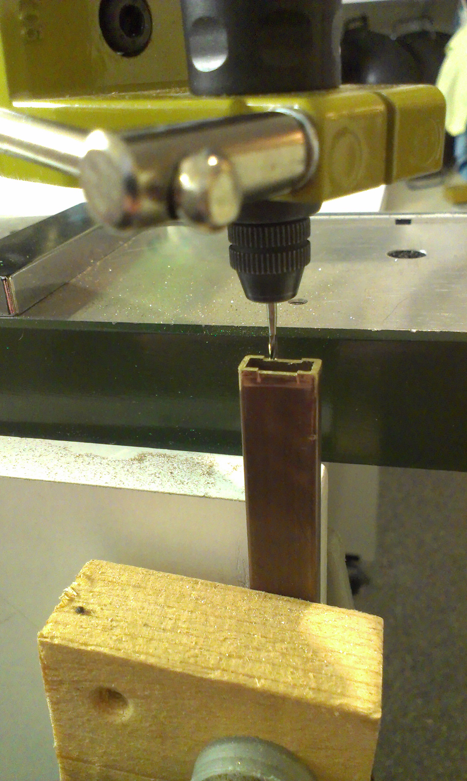
The returnloss of the feed, mounted in the dish, without any matching/tuning screw was determined to be ~10dB by Jos at Heelweg Microwave meeting 2014.