AD9835 DDS
While I was experimenting with a receive-converter for 70MHz, I came to the conclusion that I need a versatile signal source.
So, I imagined that building a (simple) DDS signal generator would be the next project inbetween developing my 70MHz transverter project.
As I had absolutely zero experience with DDS chips, I started gathering information on the web and finding suitable DDS chips.
For starters, I arrived at Analog Devices range of DDS chips, and the AD9835 to be more specific.
The biggest challenge is the form factor of the modern DDS (and PLL synthesizer) chips. I imagined/hoped that a TSSOP (4,4mm) chip would be feasable to mount on a d.i.y. made PCB. So I started designing some experimental PCB's and try produce PCB's and to mount some TSSOP chips. After some experimenting, and when it appeared to be possible to make a good sharp PCB with 0,3mm trace width, I started to gain some practice in mounting/soldering TSSOP chips to the PCB (using some heatgun-desoldered chips from an old PC mainboard). After viewing some video's on Youtube about how to solder TSSOP chips, I repeated the steps and the result was very satisfactory.
Then I designed a PCB for the AD9835 DDS chip. A simple board was quickly designed, with only the DDS chip, the necessary decoupling capacitors, voltage regulators and SPI-interface for connection to an MCU (PIC microcontroller) which will be described later on. Schematic of the DDS board:
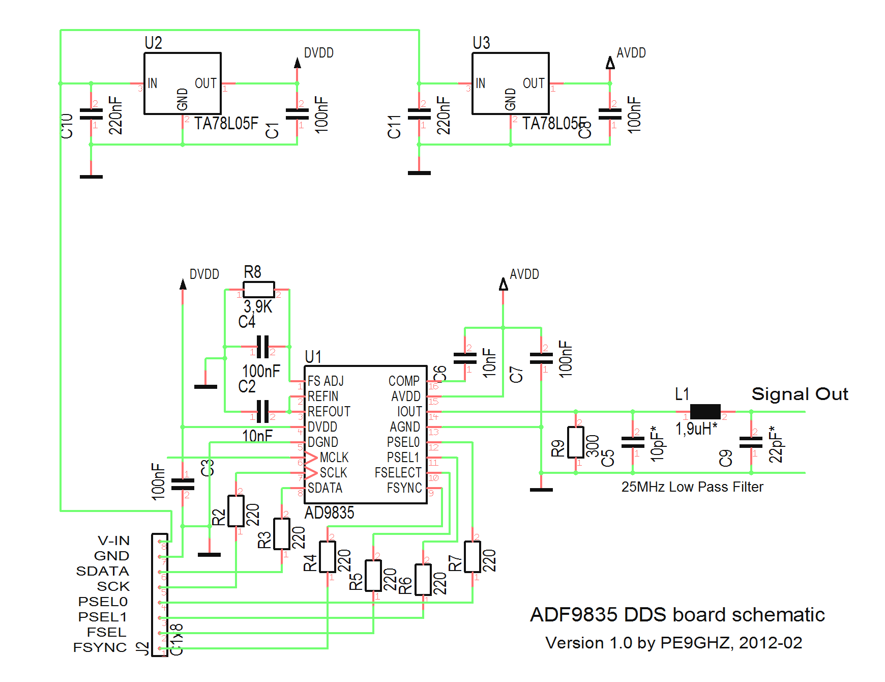
Notice that the MCLK (Master Clock) input of the DDS chip is not connected to anything. In the real world, this should be connected to a clock oscillator of maximum 50MHz. For space and design reasons, I planned this oscillator block on the back (copper ground plane) and the MCLK track ends in a pad.
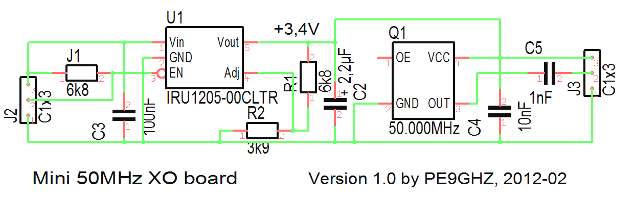
Eventually, I obtained a miniature smd mount 50MHZ Xtal Oscillator (EuroQuartz XO91050UITA), for which I designed a small piggy-back PCB. with it's own 3,3V regulator on board. Actual board size is 27 x 14mm
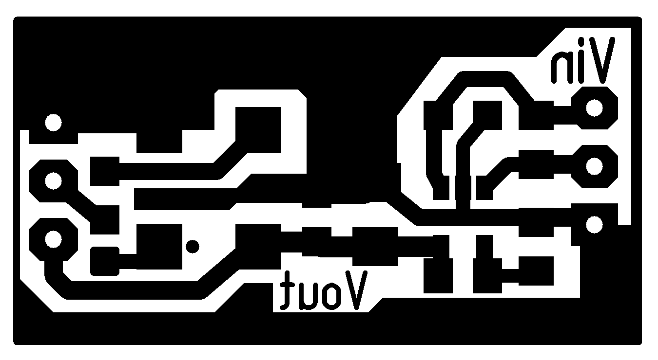
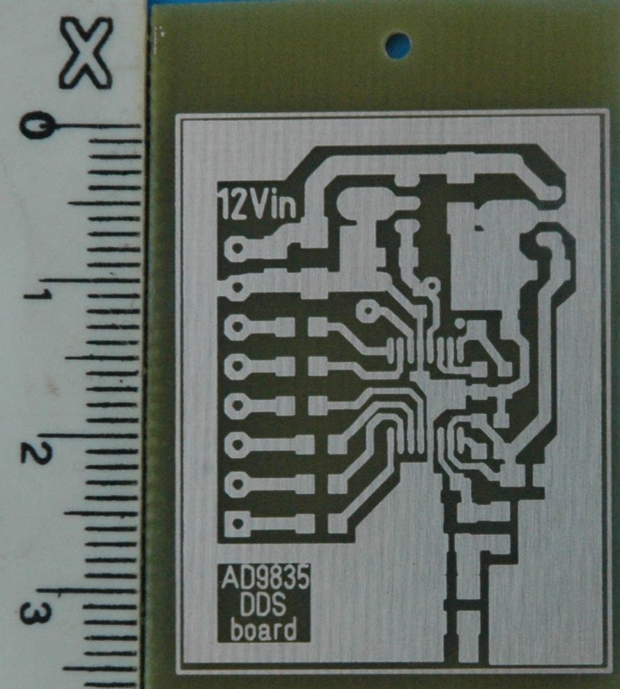
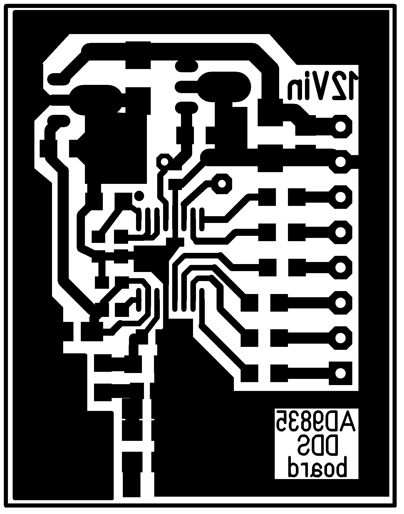
Finished DDS PCB and the DDS PCB artwork (mirrored), the actual board size is 35,5 x 27,5mm (right click, view image for full resolution):
To be continued...
Assembling the PCB
Programming DDS with a PIC microcontroller
Developing controller software
Page modified by Eddy on 2012-03-06
Previous page: 70MHz
Next page: PowerPole Distribution block